Difference between revisions of "Waris"
| (73 intermediate revisions by 3 users not shown) | |||
| Line 22: | Line 22: | ||
== Types of Radios == | == Types of Radios == | ||
| + | |||
| + | Radios are selected by model and the radio assembly is called a Tanapa/TANAPA<ref name=w5txr>https://www.w5txr.net/Motorola-History.html</ref>. The board Tanapa can be different and is what is in the codeplug FDB. | ||
| + | <blockquote> | ||
| + | Tanapa is a Japanese term But a Motorola adopted the word from the Japanese manufacturing industry meaning Kit or Partial Assembly | ||
| + | What happens during the manufacturing process, the Tanapa is assigned to items like a | ||
| + | Frame or Partial item number. As it goes through the Build process, it will finally | ||
| + | become a Radio, ( or completed accessory ) and thus a Model / Serial Number ( or Part Number ) will be assigned when completed.<ref name=w5txr>https://www.w5txr.net/Motorola-History.html</ref> | ||
| + | </blockquote> | ||
| + | Hence, one will see Tanapa on all kinds of | ||
| + | Motorola items Boards , Completed Radios, Frames, | ||
| + | Kits, Labels, etc. | ||
| + | |||
| + | [[media:Waris US Upgrade Kit Complete TANAPA and Model Number Descriptions.txt|I have a list of all US Model numbers, Tanapa's, features and codeplug versions]] | ||
| + | |||
=== HT's === | === HT's === | ||
| Line 30: | Line 44: | ||
'''HT1250ls''' - limited version of the HT1250, normally missing MDC on conventional | '''HT1250ls''' - limited version of the HT1250, normally missing MDC on conventional | ||
| + | |||
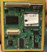
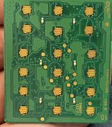
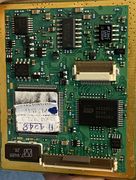
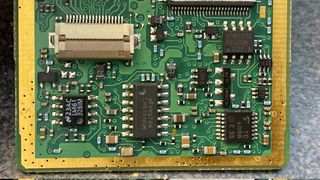
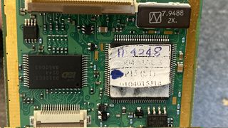
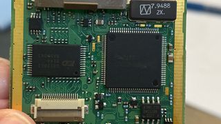
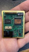
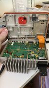
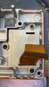
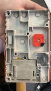
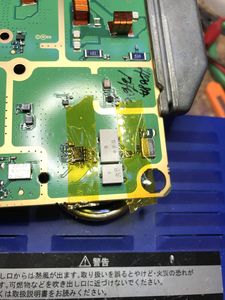
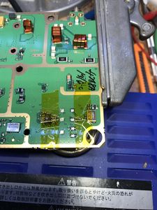
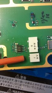
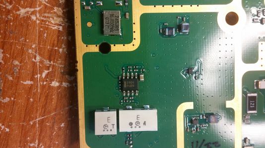
| + | [[HT1250 UHF1 PMUE1711B]] Pictures of a UHF R1 HT1250 with all shields removed. | ||
| + | |||
'''HT1550xls''' - 4 line display radio, 160 channels, VHF/UHF only | '''HT1550xls''' - 4 line display radio, 160 channels, VHF/UHF only | ||
| Line 103: | Line 120: | ||
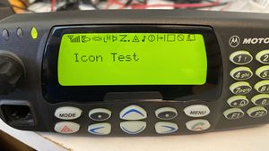
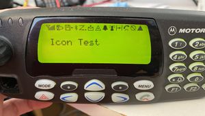
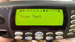
It's possible to put a 4 line control head on a Waris mobile. This can be the control head from the MTM700 as well, but the LCD ICONS will be different. | It's possible to put a 4 line control head on a Waris mobile. This can be the control head from the MTM700 as well, but the LCD ICONS will be different. | ||
| + | |||
| + | '''''Why do you want to?''''' | ||
| + | * Enables you to control VOX status from the control head | ||
| + | * Shows the frequency and PL/DPL tone on the display | ||
| + | * You need another clock to set | ||
| + | * You get to be cool | ||
| + | |||
[[File:GM380 Dispaly.JPG|thumb|GM380 LCD Icons]] | [[File:GM380 Dispaly.JPG|thumb|GM380 LCD Icons]] | ||
| Line 114: | Line 138: | ||
==== 4 Line Display Use ==== | ==== 4 Line Display Use ==== | ||
| + | |||
First ensure your display works before going further. If it's the MTM700 LCD or Display module, the Icons will be different, scan will show up as a period on it for example. The keys will be different and the Menu key can be especially confusing. | First ensure your display works before going further. If it's the MTM700 LCD or Display module, the Icons will be different, scan will show up as a period on it for example. The keys will be different and the Menu key can be especially confusing. | ||
| Line 119: | Line 144: | ||
* Check your codeplug | * Check your codeplug | ||
** is the existing codeplug a Major version 3? Does it have an FDB2 size of 0x09? If not, you'll have to get a binary codeplug and push it into the radio that is | ** is the existing codeplug a Major version 3? Does it have an FDB2 size of 0x09? If not, you'll have to get a binary codeplug and push it into the radio that is | ||
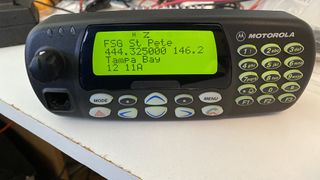
| − | ** This is done by selecting a default codeplug that matches your needs closely. I find a code plug that has analog only, no LTR and the options I need. Then I edit this codeplug in a hex editor and | + | ** This is done by selecting a default codeplug that matches your needs closely. I find a code plug that has analog only, no LTR and the options I need. Then I edit this codeplug in a hex editor and paste it from 0x280 to the end into the existing codeplug. Using the [https://github.com/W9CR/CPSsrec tools to convert this to an srec file] makes it easy to open in CPS with out needing to write it to a radio. |
** once this is working how you like it, program it into the radio using Codeplug tool. | ** once this is working how you like it, program it into the radio using Codeplug tool. | ||
* connect up your control head and enjoy! | * connect up your control head and enjoy! | ||
| Line 131: | Line 156: | ||
CDM 1850 with GM380 LCD.JPG | CDM 1850 with GM380 LCD.JPG | ||
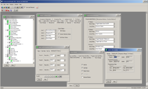
Waris CPS with CDM1850 220 Mhz.png | Waris CPS with CDM1850 220 Mhz.png | ||
| + | </gallery> | ||
| + | |||
| + | ===== Low Band 4 Line Display ===== | ||
| + | I did some work recently on these for low band. Note that lowband didn't have any default codeplugs for the 4 line, N, display. | ||
| + | |||
| + | I have made the following codeplugs for lowband with these features: | ||
| + | |||
| + | * 42-54 MHz | ||
| + | * Tuning and test frequencies corrected | ||
| + | * Region 1 | ||
| + | * Blank Serial | ||
| + | * AA only, no trunking | ||
| + | * QCII, MDC, and DTMF signaling enbled | ||
| + | * 52.525 Channel 1 | ||
| + | |||
| + | There is a binary file and an srecord that can be opened in CPS. | ||
| + | |||
| + | Note that if you want to use this Binary file and have the tuning piers set, you'll need to retune the radio. The other option is to take your tuning data and modify it. This can be done via waris.py or by using the data below | ||
| + | |||
| + | At offset 0x139 replace the tuning piers: | ||
| + | 112D122513291469158115F91789112D122513291469158115F91789 | ||
| + | with | ||
| + | 112B12BB145515E9177E19131AA8112B12BB145515E9177E19131AA8 | ||
| + | |||
| + | At offset 0x1C8 replace the test channels: | ||
| + | 1135113a1225121113291315146914551581156d15f915e51766176b | ||
| + | with | ||
| + | 1135113912BB12A71455144015E915D5177E176A191318FF1A851A8A | ||
| + | |||
| + | If using waris.py set the tuning channels as follows for RX and TX 1-7 | ||
| + | 41.975 43.975 46.025 48.050 50.075 52.100 54.125 | ||
| + | |||
| + | The Test Channels are | ||
| + | TX RX | ||
| + | 42.025 42.050 | ||
| + | 43.975 43.875 | ||
| + | 46.025 45.925 | ||
| + | 48.050 47.950 | ||
| + | 50.075 49.975 | ||
| + | 52.100 52.000 | ||
| + | 53.950 53.975 | ||
| + | |||
| + | To use these files, decide how you want to do it, ie preserve your tuning data or not. As you're moving the tuning piers, you have to retune anyways, so I would use Codeplug tool and write the entire binary codeplug in, then retune. However many people don't want to do this, and you can just merge your radio, and write it from 0x280-end, preserving the tuning area. | ||
| + | |||
| + | [[media:42-54mhz-1850 Default Srecord Format.srec|42-54mhz-1850 Default Srecord Format.srec]] - 42-54mhz CDM 1850 Default Codeplug in Srecord Format | ||
| + | |||
| + | This is based on a M25DKF9AA5A model, IMUB6002A Tanapa, a low band 3 conventional radio. | ||
| + | |||
| + | [[media:42-54mhz-1850 Default Binary Format.bin|42-54mhz-1850 Default Binary Format.bin]] - 42-54mhz CDM 1850 Default Codeplug in Binary Format | ||
| + | |||
| + | If you want to write the codeplug into your radio | ||
| + | |||
| + | <gallery mode=packed-hover widths=300px> | ||
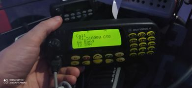
| + | CDM1850 6 meters.jpg | ||
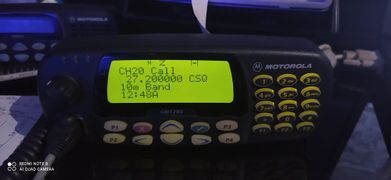
| + | CDM1850 10 meters.jpg | ||
</gallery> | </gallery> | ||
| Line 141: | Line 221: | ||
=== AAHLN9729C - DTMF decode board === | === AAHLN9729C - DTMF decode board === | ||
=== AAENLN4150A - Mandown board === | === AAENLN4150A - Mandown board === | ||
| + | |||
| + | The Mandown Option Board is compatible with all 5-Tone, MPT and MDC/Conv portable radios of | ||
| + | the Professional Radio Series in all bands (except P040/P080 and GP320). | ||
| + | |||
| + | It is also operational with all connected original Motorola accessories for the GP Professional Radios | ||
| + | Series portables. | ||
| + | |||
| + | Installation in any Intrinsically Safe (IS) radios will invalidate the radio’s IS approval (i.e. FM-radios). | ||
| + | |||
| + | [[Media:Mandown Option Board ENLN4150A Study Guide 68P64121B10.pdf|Mandown Option Board ENLN4150A Study Guide 68P64121B10]] Manual | ||
| + | |||
| + | [[Media:WARIS Mandown OSS R01.01.01 2001-01-11.zip|WARIS Mandown OSS R01.01.01 2001-01-11]] Programing Software - Mandown Option Board Service Software | ||
| + | |||
=== Passport board - PTCB === | === Passport board - PTCB === | ||
| Line 162: | Line 255: | ||
CDM With Option Board Case.JPG | CDM With Option Board Case.JPG | ||
</gallery> | </gallery> | ||
| + | |||
| + | ==== Software ==== | ||
| + | |||
| + | Passport uses it own firmware and CPS to program the PTCB. There is a complex interaction of programing of the option board and the radio it self. | ||
| + | |||
| + | [[Media:PassPort CPS R03.02.00.zip|PassPort CPS R03.02.00]] | ||
| + | |||
| + | [[Media:PassPort CPS R04.00.01.zip|PassPort CPS R04.00.01]] | ||
| + | |||
| + | [[Media:PassPort CPS R04.03.24.zip|PassPort CPS R04.03.24]] | ||
| + | |||
| + | [[Media:PassPort ServicePak R07.02.09.zip|PassPort ServicePak R07.02.09]] | ||
| + | |||
| + | [[Media:PassPort ServicePak R08.02.07.zip|PassPort ServicePak R08.02.07]] | ||
| + | |||
| + | [[Media:PassPort CPS R05.00.14.zip|PassPort CPS R05.00.14]] | ||
| + | |||
| + | [[Media:PassPort R05.02.04.zip|PassPort R05.02.04]] | ||
| + | |||
| + | ==== Passport Docs ==== | ||
| + | |||
| + | [[Media:PassPort Data Configuration Guide.pdf|PassPort Data Configuration Guide]] | ||
| + | |||
| + | [[Media:PassPort RSSI Charts.pdf|PassPort RSSI Charts]] | ||
| + | |||
| + | [[Media:PassPort Site Search.pdf|PassPort Site Search]] | ||
| + | |||
| + | [[Media:PassPort Software Compatibility.pdf|PassPort Software Compatibility]] | ||
| + | |||
| + | [[Media:THEORY OF OPERATION PASSPORT SITE SEARCH.pdf|THEORY OF OPERATION: PASSPORT SITE SEARCH]] | ||
| + | |||
| + | [[Media:PassPort CPS R03.02.00 Programming Hints.pdf|PassPort CPS R03.02.00 Programming Hints]] | ||
| + | |||
| + | |||
| + | ===== Release Notes ===== | ||
| + | |||
| + | |||
| + | |||
| + | [[Media:PassPort Firmware R06.02.13 - Release Notes 122002.pdf|PassPort Firmware R06.02.13 - Release Notes 122002]] | ||
| + | |||
| + | [[Media:PassPort Firmware R06.02.14 - Release Notes 042003.pdf|PassPort Firmware R06.02.14 - Release Notes 042003]] | ||
| + | |||
| + | [[Media:PassPort Firmware R06.02.16 Customer Release Notes.pdf|PassPort Firmware R06.02.16 Customer Release Notes]] | ||
| + | |||
| + | [[Media:PassPort Firmware R06.02.16 - Release Notes.pdf|PassPort Firmware R06.02.16 - Release Notes]] | ||
| + | |||
| + | [[Media:PassPort Firmware R07.01.11 - Release Notes 112003.pdf|PassPort Firmware R07.01.11 - Release Notes 112003]] | ||
| + | |||
| + | [[Media:PassPort Firmware R07.01.19 Release Notes.pdf|PassPort Firmware R07.01.19 Release Notes]] | ||
| + | |||
| + | [[Media:PassPort Firmware R07.02.09 Release Notes.pdf|PassPort Firmware R07.02.09 Release Notes]] | ||
| + | |||
| + | [[Media:PassPort Firmware R08.02.05 Release Notes.pdf|PassPort Firmware R08.02.05 Release Notes]] | ||
| + | |||
| + | [[Media:PassPort Firmware R08.02.06 Release Notes.pdf|PassPort Firmware R08.02.06 Release Notes]] | ||
| + | |||
| + | [[Media:PassPort Firmware R08.02.07 Release Notes.pdf|PassPort Firmware R08.02.07 Release Notes]] | ||
| + | |||
| + | [[Media:PassPort Firmware R08.00.17 Release Notes.pdf|PassPort Firmware R08.00.17 Release Notes]] | ||
| + | |||
| + | :: Service pack | ||
| + | |||
| + | [[Media:PassPort Firmware R06.02.13 ServicePak - Release Notes 122002.pdf|PassPort Firmware R06.02.13 ServicePak - Release Notes 122002]] | ||
| + | |||
| + | [[Media:PassPort Firmware R06.02.14 ServicePak - Release Notes 042003.pdf|PassPort Firmware R06.02.14 ServicePak - Release Notes 042003]] | ||
| + | |||
| + | [[Media:PassPort R06.02.16 ServicePak - Release Notes.pdf|PassPort R06.02.16 ServicePak - Release Notes]] | ||
| + | |||
| + | [[Media:PassPort CPS R03.02.00 Customer Release Notes.pdf|PassPort CPS R03.02.00 Customer Release Notes]] | ||
| + | |||
| + | [[Media:PassPort CPS R04.00.00 - Release Notes.pdf|PassPort CPS R04.00.00 - Release Notes]] | ||
| + | |||
| + | [[Media:PassPort CPS R05.00.10 Release Notes.pdf|PassPort CPS R05.00.10 Release Notes]] | ||
| + | |||
| + | [[Media:PassPort CPS R05.00.14 Release Notes.pdf|PassPort CPS R05.00.14 Release Notes]] | ||
=== Unknown Boards === | === Unknown Boards === | ||
| Line 184: | Line 352: | ||
[https://batboard.batlabs.com/viewtopic.php?t=83543 Here is a comment] posted by the developer of this board on batlabs forum | [https://batboard.batlabs.com/viewtopic.php?t=83543 Here is a comment] posted by the developer of this board on batlabs forum | ||
| + | |||
| + | == Common Parts == | ||
| + | |||
| + | The majority of the Waris radios, HT and Mobile are basically the same design. There are number of common parts between them and the custom chips are shared | ||
| + | |||
| + | * ASFIC - This is a custom part that generates CPU clock, filters audio (TX/RX), controls parts of the radio (VCO/PA/etc) and does the PL/DPL and signaling. It's early similar to a [https://www.cmlmicro.com/wp-content/uploads/2017/06/CMX7031_7041_FI1_data-sheet.pdf CML7041], both are 48 pin QFP's | ||
= Programming and Flash Cables = | = Programming and Flash Cables = | ||
| Line 213: | Line 387: | ||
* [http://www.ebay.com/itm/201399649953 2 in 1 prolific cable for Waris and CDM] | * [http://www.ebay.com/itm/201399649953 2 in 1 prolific cable for Waris and CDM] | ||
* [https://www.amazon.com/gp/product/B00ED2UMMC Valley Enterprises® 5 in 1 FTDI USB Programming Cable Motorola Mobile and Portables] | * [https://www.amazon.com/gp/product/B00ED2UMMC Valley Enterprises® 5 in 1 FTDI USB Programming Cable Motorola Mobile and Portables] | ||
| + | |||
| + | ==== Flash Modification ==== | ||
| + | <blockquote> I've modified my 5-in-1 Valley Cable with switches on the side and an extra pin on the boot contact to enable flashing the EX and HT/Pro line of radios. | ||
| + | |||
| + | I used the following parts from Digi-Key to do this | ||
| + | * 450-1635-ND - Slide Switch | ||
| + | * 952-3135-1-ND - Contact Spring (POGO pin) | ||
| + | |||
| + | You'll need to drill out the right part of the pcb on the connector and epoxy the switch in place, but it's very continent to have it in place. | ||
| + | |||
| + | </blockquote> | ||
Be sure you use the proper drivers if using the prolific cable. | Be sure you use the proper drivers if using the prolific cable. | ||
| Line 223: | Line 408: | ||
The official upgrade kit includes default codeplugs, firmware images and boot images. These are in an encrypted format, and it appears the unofficial kit has decoded these as the included codeplugs/firmware. | The official upgrade kit includes default codeplugs, firmware images and boot images. These are in an encrypted format, and it appears the unofficial kit has decoded these as the included codeplugs/firmware. | ||
| + | |||
| + | The official kit does this: | ||
| + | # Reads the codeplug and firmware info (at 9600 BPS) | ||
| + | # determines if it can upgrade based of #1 | ||
| + | # puts it bootstrap mode | ||
| + | # loads the boot helper program via serial (at 2211 BPS) | ||
| + | # Boothelper runs from 0x0080 and erases the flash | ||
| + | # updater loads the firmware image at the baud rate set by the boot helper program | ||
| + | # updated then pushes the codeplug in at this baud rate too. | ||
| + | |||
| + | Note that the FL0 CPU needs the data sent at 2211 BPS, but the computer can only write at 2400 bps. This is 8% too fast. This 2x the rated baud speed difference from the 68HC11 reference manual! | ||
| + | |||
| + | <blockquote> | ||
| + | For 8-bit data format, the baud-rate variation that can be tolerated is about ±4.5 percent; for 9-bit data format, the variation is about ±4 percent. This analysis assumes one of the devices was operating at the exact baud-rate frequency, and the calculations show how much the other device could vary from this. One device operating four percent too slow cannot communicate with another device operating 4 percent too fast. | ||
| + | </blockquote> | ||
| + | |||
| + | '''What this means is if your computer's async port is running just a bit faster (RS232 gives a 3.5% error as acceptable for baud rate), the error can be too much for the radio and it will fail to load the boot helper code and thus won't flash.''' | ||
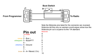
[[File:Waris CDM flash cable.png|thumb|center|Flash adapter for CDM1250 radio]] | [[File:Waris CDM flash cable.png|thumb|center|Flash adapter for CDM1250 radio]] | ||
| + | |||
| + | = Cables = | ||
| + | |||
| + | == CDM Accessory Connector == | ||
| + | |||
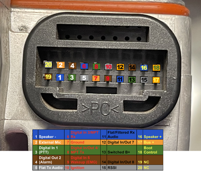
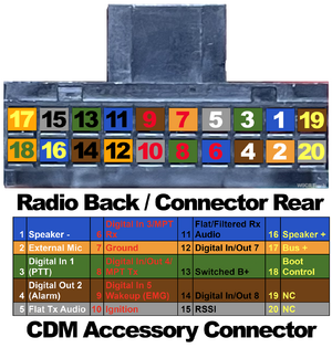
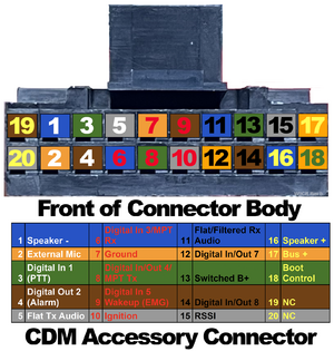
| + | The CDM750/CDM1250/CDM1550/Pro Mobile pinout for the accessory connector is below. | ||
| + | |||
| + | Note that is uses Motorola's pinout for the connector which is designed to retain compatibility with the prior (Radius) radios. | ||
| + | |||
| + | [[File:Waris Accessory Connector Back Of Radio.png|thumb|right|400px|Waris accessory connector from back of radio]] | ||
| + | [[File:Waris Back Of Accessory Diagram.png|thumb|right|300px|Waris accessory connector back view]] | ||
| + | [[File:Waris Front Of Accessory Diagram.png|thumb|right|300px|Waris accessory connector front view]] | ||
| + | {| class="wikitable" | ||
| + | !colspan="3"|CDM Accessory Port Pin Out | ||
| + | |- | ||
| + | ! Function | ||
| + | ! Pin | ||
| + | ! Notes | ||
| + | |- | ||
| + | | style="font-weight: bold;color:#FFFFFF; background-color: #2754c5"| Speaker - | ||
| + | | style="font-weight: bold;color:#FFFFFF; background-color: #2754c5"| 1 | ||
| + | | This is a floating output, don't connect to ground. | ||
| + | |- | ||
| + | | style="font-weight: bold;color:#FFFFFF; background-color: #f19d39"| External Mic | ||
| + | | style="font-weight: bold;color:#FFFFFF; background-color: #f19d39"| 2 | ||
| + | | This is controlled by the settings in the personality for emphasis, high-pass filtered | ||
| + | |- | ||
| + | | style="font-weight: bold;color:#FFFFFF; background-color: #48752c"| Digital In 1 (PTT) | ||
| + | | style="font-weight: bold;color:#FFFFFF; background-color: #48752c"| 3 | ||
| + | | Take this to ground to PTT | ||
| + | |- | ||
| + | | style="font-weight: bold;color:#FFFFFF; background-color: #714216"| Digital Out 2 (Alarm) | ||
| + | | style="font-weight: bold;color:#FFFFFF; background-color: #714216"| 4 | ||
| + | | This goes to 12v high. | ||
| + | |- | ||
| + | | style="font-weight: bold;color:#FFFFFF; background-color: #999999"| Flat Tx Audio | ||
| + | | style="font-weight: bold;color:#FFFFFF; background-color: #999999"| 5 | ||
| + | | Digital audio, this is always flat no matter the settings of the personality and is not highpass filtered | ||
| + | |- | ||
| + | | style="font-weight: bold;color:#ed0728; background-color: #2754c5"|Digital In 3/MPT Rx | ||
| + | | style="font-weight: bold;color:#ed0728; background-color: #2754c5"| 6 | ||
| + | | 5v logic | ||
| + | |- | ||
| + | | style="font-weight: bold;color:#ed0728; background-color: #f19d39"|Ground | ||
| + | | style="font-weight: bold;color:#ed0728; background-color: #f19d39"|7 | ||
| + | | | ||
| + | |- | ||
| + | | style="font-weight: bold;color:#ed0728; background-color: #48752c"|Digital In/Out 4/ MPT Tx | ||
| + | | style="font-weight: bold;color:#ed0728; background-color: #48752c"|8 | ||
| + | | 5v logic | ||
| + | |- | ||
| + | | style="font-weight: bold;color:#ed0728; background-color: #714216"|Digital In 5 Wakeup (EMG) | ||
| + | | style="font-weight: bold;color:#ed0728; background-color: #714216"|9 | ||
| + | | This is the emergency function, if programed it will transmit an emergency signal when grounded. If the radio is off, and it's grounded the radio will wakeup. If programed as emergency it will tranmit the emergency after waking up. <br> Tying it to 7(ground) will power on the radio when it has power applied. | ||
| + | |- | ||
| + | | style="font-weight: bold;color:#ed0728; background-color: #999999"|Ignition | ||
| + | | style="font-weight: bold;color:#ed0728; background-color: #999999"|10 | ||
| + | | Ignition sense, 12v here will power the radio up if programed. | ||
| + | |- | ||
| + | | style="font-weight: bold;color:#000000; background-color: #2754c5"|Flat/Filtered Rx Audio | ||
| + | | style="font-weight: bold;color:#000000; background-color: #2754c5"|11 | ||
| + | | This audio response is determined in the programing per personality whether it's flat or de-emphasized | ||
| + | |- | ||
| + | | style="font-weight: bold;color:#000000; background-color: #f19d39"|Digital In/Out 7 | ||
| + | | style="font-weight: bold;color:#000000; background-color: #f19d39"|12 | ||
| + | | 5v Logic | ||
| + | |- | ||
| + | | style="font-weight: bold;color:#000000; background-color: #48752c"|Switched B+ | ||
| + | | style="font-weight: bold;color:#000000; background-color: #48752c"|13 | ||
| + | | 12v here when the radio is powered on, can source 1 amp (fuse it) from a deticated LM2941 regulator | ||
| + | |- | ||
| + | | style="font-weight: bold;color:#000000; background-color: #714216"|Digital In/Out 8 | ||
| + | | style="font-weight: bold;color:#000000; background-color: #714216"|14 | ||
| + | | 5v Logic | ||
| + | |- | ||
| + | | style="font-weight: bold;color:#000000; background-color: #999999"|RSSI | ||
| + | | style="font-weight: bold;color:#000000; background-color: #999999"|15 | ||
| + | | Direct from the SA616 IF IC, this can do >90 dB of dynamic range and is tempeture compensated to within 2dB. | ||
| + | |- | ||
| + | | style="font-weight: bold;color:#ffff54; background-color: #2754c5"|Speaker + | ||
| + | | style="font-weight: bold;color:#ffff54; background-color: #2754c5"|16 | ||
| + | | This is a floating output, don't connect to ground. | ||
| + | |- | ||
| + | | style="font-weight: bold;color:#ffff54; background-color: #f19d39"|Bus + | ||
| + | | style="font-weight: bold;color:#ffff54; background-color: #f19d39"|17 | ||
| + | | TX/RX SBEP data | ||
| + | |- | ||
| + | | style="font-weight: bold;color:#ffff54; background-color: #48752c"|Boot Control | ||
| + | | style="font-weight: bold;color:#ffff54; background-color: #48752c"|18 | ||
| + | | Bring this to ground to put in boot loader mode | ||
| + | |- | ||
| + | | style="font-weight: bold;color:#ffff54; background-color: #714216"|NC | ||
| + | | style="font-weight: bold;color:#ffff54; background-color: #714216"|19 | ||
| + | | Not Connected | ||
| + | |- | ||
| + | | style="font-weight: bold;color:#ffff54; background-color: #999999"|NC | ||
| + | | style="font-weight: bold;color:#ffff54; background-color: #999999"|20 | ||
| + | | Not Connected | ||
| + | |} | ||
| + | |||
| + | Notes: | ||
| + | Ignition sense should be used to power the radio on, and fused with a 1amp fuse. The wakeup/emergency function can be used, but if you program it as emergency the results will be unexpected. | ||
| + | |||
| + | <br> | ||
| + | :'''RSSI output''' | ||
| + | <blockquote> | ||
| + | This is direct from the SA616 IF IC, and per the [[Media:SA616 IFIC DataSheet.pdf|datasheet]], it is calibrated and tempeture compensated to within 2 dB over 80 db of range. The CDM service manual rates this as a linear range of 70 dB, and indeed the range is generally linear from -120 to -55 dBm of input signal. | ||
| + | </blockquote> | ||
| + | <br> | ||
| + | |||
| + | Signal Voltage | ||
| + | -135 0.793 | ||
| + | -130 0.823 | ||
| + | -120 0.912 | ||
| + | -110 1.120 | ||
| + | -100 1.326 | ||
| + | -90 1.563 | ||
| + | -80 1.758 | ||
| + | -70 1.945 | ||
| + | -60 2.192 | ||
| + | -55 2.323 | ||
| + | -50 2.347 | ||
| + | -40 2.394 | ||
| + | -30 2.420 | ||
| + | |||
| + | The accessory connector is a TE AMP connector [https://www.digikey.com/product-detail/en/te-connectivity-amp-connectors/104422-2/104422-2-ND/550725 Digi-key part number 104422-2-ND], and uses [https://www.digikey.com/product-detail/en/te-connectivity-amp-connectors/86016-2/A25989-ND/290676 Digi-Key Part number A25989-ND] for the pins. | ||
| + | |||
| + | This is the same series used by the Radius and Maxtrac radios and much like an RJ45/RJ11 connector the smaller connectors will work for everything other than flashing or programing the Pro Series mobiles. What this means is accessories for the radius (R.I.C.K., Etc.) will work on the CDM with no modifications. Refer to the image below to see how this works. | ||
| + | |||
| + | [[File:Waris vs Radius 16 pin vs 20 pin accessory connector.png|thumb|center| 300px| Waris vs Radius 16 pin vs 20 pin accessory connector]] | ||
| + | |||
| + | == CDM Mic cable == | ||
| + | |||
| + | The CDM uses a 10P10C modular plug. | ||
| + | |||
| + | CDM DTMF Mic colors to pins, this is useful to know if the tab breaks off the mic and needs to be replaced. | ||
| + | |||
| + | Looking at the plug with the tab facing down, the leftmost is pin 1 and the right most is 10. | ||
| + | {| class="wikitable" | ||
| + | |- | ||
| + | ! Pin !! Color | ||
| + | |- | ||
| + | | 1 || White | ||
| + | |- | ||
| + | | 2 || Violet | ||
| + | |- | ||
| + | | 3 || OPEN | ||
| + | |- | ||
| + | | 4 || Blue | ||
| + | |- | ||
| + | | 5 || Black | ||
| + | |- | ||
| + | | 6 || Red | ||
| + | |- | ||
| + | | 7 || Green | ||
| + | |- | ||
| + | | 8 || OPEN | ||
| + | |- | ||
| + | | 9 || Brown | ||
| + | |- | ||
| + | | 10 || Yellow | ||
| + | |} | ||
| + | |||
| + | <gallery> | ||
| + | image of connector.jpg | ||
| + | </gallery> | ||
| + | |||
| + | == Professional Series HT's == | ||
| + | |||
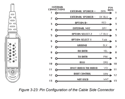
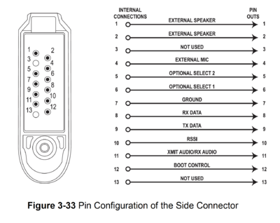
| + | this is the pinout for the HT750/1250/1550 and Pro series HT's | ||
| + | |||
| + | [[File:Waris Side Connector Pinout HT750-HT1250-HT1550 MTX850-MTX8250-MTX950-MTX9250 GP318-GP320-GP238-GP338-GP340-GP380-GP640 PR860-PRO5150-PRO5500.png|thumb|center|400px|Waris Side Connector Pinout ]] | ||
| + | |||
| + | This is the pinout for the Expert Series, EX500/EX600 radios. | ||
| + | |||
| + | [[File:EX500, EX560XLS, EX600, EX600XLS, GP688, GP328+ Portable Side Connector.png|thumb|center|400px|Expert Series EX500, EX560XLS, EX600, EX600XLS, GP688, GP328+ Portable Side Connector]] | ||
= 220 HT1250ls and CDM 1550ls = | = 220 HT1250ls and CDM 1550ls = | ||
| Line 293: | Line 671: | ||
Using Chirp is the way to do it and you can change everything. I typically set the signaling bits to FF enabling all signaling supported, but some radios may not work with this. Always read the radio and save the data before making changes. The data file format is the same binary on the radio EEPROM and use by cptool. | Using Chirp is the way to do it and you can change everything. I typically set the signaling bits to FF enabling all signaling supported, but some radios may not work with this. Always read the radio and save the data before making changes. The data file format is the same binary on the radio EEPROM and use by cptool. | ||
| − | === old way === | + | === Process Overview === |
| + | |||
| + | Simple steps: | ||
| + | |||
| + | # Use CP tool to read the radio from 0x000 to 0x3FFF. Save this file. This is your savior if you fuck anything else up. This is the tuning data, feature data and programing data. _SAVE_ this file. If you don't do this and email me about it, I'll screen shot it and share it on social media. Several thousand people will enjoy the laugh. | ||
| + | # ensure the radio is on the last firmware. If not, update it using the firmware tool. This will nuke the programing and features, but will not mess with the tuning. | ||
| + | ## if you want to get the programing and features back into it, take your backup and program the radio from 0x300 to the end with that. This should work and only will program the programing partition of the flash. | ||
| + | # Use chirp + waris.py to read the waris tuning data. Make your changes to the serial and model number, channels, band edges, tuning piers, and anything else here. Program it into the radio. | ||
| + | # read the radio in CPS. If it works you're good to go. | ||
| + | # If you changed the tuning pier frequencies, you'll need to retune the radio in tuner. Same for the wideband squelch in the 220 radio. | ||
| + | |||
| + | After you get all this done, and are happy with it, do step 1 again. | ||
| + | |||
| + | ==== old way ==== | ||
This is easiest with [[media:Waris Codeplugtool.zip|CP tool]] and a hex editor. | This is easiest with [[media:Waris Codeplugtool.zip|CP tool]] and a hex editor. | ||
| Line 341: | Line 732: | ||
Once you're done with all this, you should have a great radio that covers 216-225 MHz, wide band FM, MDC/QCII/DTMF, 30W power out, and damn sensitive squelch. | Once you're done with all this, you should have a great radio that covers 216-225 MHz, wide band FM, MDC/QCII/DTMF, 30W power out, and damn sensitive squelch. | ||
| + | |||
| + | = Mobile Power Amp = | ||
| + | |||
| + | The CDM is available in a high and low power version for VHF and UHF. The nice thing about the low power units is they can go from 1-25w and while the high power are 20-45w. As sometimes the link radios are best run at low power or if building a repeater it's much better to run a low power radio at 15W into an external PA then a high power radio at 20w. A solid state RF amp wants to be run within 3dB of it's rated output. While you can run a 45w radio at 20w, you'll find it's drawing double the power of the 25w radio running at 20w. This extra power is turned to heat, and heat kills power amps. | ||
| + | |||
| + | The PA of the radios can be either LDMOS or BiPolar, and I've only tested this with the LDMOS. | ||
| + | |||
| + | Sometimes I've had need of a low power radio, but only have a high power. In these cases I disable half the final output device Q4441, a [https://www.nxp.com/docs/en/data-sheet/MRF1570N.pdf MRF1570]. This is accomplished by removing C4428 and L4421, then placing a 100 ohm (not critical) resistor in place of C4422. This effectively disables half the device and makes it into a MRF1535 which is the device used in the low power radios. | ||
| + | |||
| + | Once this is done, convert the radio to a low power radio by editing the codeplug and then re-align it. | ||
| + | |||
| + | I have several UHF2 high-power running for years in this fashion. | ||
= UHF 450-527 Ham Band Mod = | = UHF 450-527 Ham Band Mod = | ||
| Line 365: | Line 768: | ||
N9IAA has reported much success moving the CDM's to cover 46-54 MHz (from 42-50 MHz) after modifying the programing using chip and changing the following parts in yellow on [https://docs.google.com/spreadsheets/d/1vWFhZXn8z1iWo6HxrNn8Le5SOv-1GtE4imuL8RZ9O00/edit?usp=sharing this spreadsheet]. A complete retuning is necessary of course. | N9IAA has reported much success moving the CDM's to cover 46-54 MHz (from 42-50 MHz) after modifying the programing using chip and changing the following parts in yellow on [https://docs.google.com/spreadsheets/d/1vWFhZXn8z1iWo6HxrNn8Le5SOv-1GtE4imuL8RZ9O00/edit?usp=sharing this spreadsheet]. A complete retuning is necessary of course. | ||
| + | |||
| + | = Audio Balance = | ||
| + | |||
| + | During a modification of the CDM1550 UHF 2 to cover 440-450 for US ham band use I attempted to align the audio response. This was necessary as I wanted to use the radio for digital use and as an analog repeater. The Waris radios use a two point modulation and are known for having a good flat response to audio when configured as such. This is important for repeater and digital use, as the deviation of a 50mv signal at 100 Hz and 1000 Hz should be the same. | ||
| + | |||
| + | '''SIMPLE TL;DR: just use 80 Hz and 2500 Hz rather than 3000 Hz as CPS instructs you''' | ||
| + | |||
| + | In the Waris accesory pins you can set the external input for three states: | ||
| + | # Flat | ||
| + | # Highpass Flat (removes everything below 300 Hz) | ||
| + | # Mic input with 6db/octave rolloff 300-3000 Hz | ||
| + | |||
| + | These are configured in two areas in the CPS: | ||
| + | Radio config > accessory config > RX Audio Type | ||
| + | > Data PTT audio source | ||
| + | > Ext. PTT audio source | ||
| + | The below are only needed if you're not running flat audio. This has the | ||
| + | advantage if you still want flat audio in and out of the radio, but want to | ||
| + | run the PL/DPL encoder and have a HPF on the flat audio output. | ||
| + | |||
| + | Personality > Advanced > Compression type | ||
| + | > Expansion type | ||
| + | > Peremphisis Selection | ||
| + | |||
| + | From the service manual: | ||
| + | <blockquote> | ||
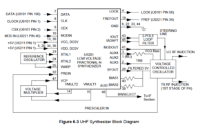
| + | In order to modulate the PLL the two spot modulation method is utilized. Via pin 10 (MODIN) on U5201 the audio signal is applied to both the A/D converter (low freq path) as well as the balance attenuator (high freq path). The A/D converter converts the low frequency analog modulating signal into a digital code that is applied to the loop divider, thereby causing the carrier to deviate. The balance attenuator is used to adjust the VCO’s deviation sensitivity to high frequency modulating signals. The output of the balance attenuator is present at the MODOUT port (U5201-41) and connected to the VCO modulation diode CR5321 via R5321, C5325. | ||
| + | </blockquote> | ||
| + | U5201 is the custom PLL chip. All I have is a diagram of it: | ||
| + | [[File:Waris UHF Synth Chip Block Diagram.png|thumb|center|Waris UHF Synth Chip Block Diagram]] | ||
| + | |||
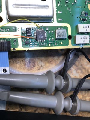
| + | Based on my reading of the description it's modulating the reference loop independently of the warp of the master oscillator. This is basically dither modulation of the reference loop. I looked at the mod input from the Audio IC, and the mod output to the VCO varactor, and they do not have any artifacts and are at the same level vs. frequency on my scope. | ||
| + | |||
| + | [[File:Waris UHF PLL Chip testing.jpg|thumb|center|Waris UHF PLL Chip testing]] | ||
| + | |||
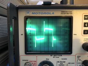
| + | The alignment procedure is to inject a 80 Hz sine wave at 100 mV amplitude (assuming it's RMS, not peak to peak), note the deviation and then inject a 3 KHz tone at the same amplitude, then adjust the tuning to make the deviation the same. After this, I got the same poor response on a 50Hz square wave input to the radio. | ||
| + | |||
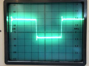
| + | [[File:Waris UHF 50 Hz Square Wave Bad Radio.jpg|thumb|center|Waris UHF 50 Hz Square Wave Bad Radio]] | ||
| + | |||
| + | This is the same test via the known good radio. Note how much less sloped the waveform is in this radio. I was never able to get the slope of the subject radio to flatten. | ||
| + | |||
| + | [[File:Waris UHF 50 Hz Square Wave known Good Radio.jpg|thumb|center|Waris UHF 50 Hz Square Wave known Good Radio]] | ||
| + | |||
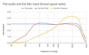
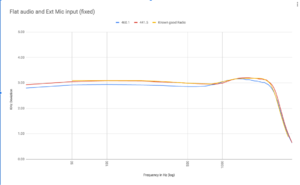
| + | I did the adjustment on a known good radio using the 80/3 KHz Motorola method and have found it's not perfect. I then aligned it the same by injecting a square wave until it's "Flat" on the service monitor. This proved to make the response very close to ideal. I suspect the Motorola suggested high frequency of 3khz is where the radio has started to roll off on the high side, and using a 2.5 KHz upper test point I was able to align the known good radio. | ||
| + | |||
| + | The alignment of this radio worked, and was within 5% of the settings as it came from the factory. | ||
| + | |||
| + | My conclusions from this: | ||
| + | |||
| + | There is likely something wrong with Motorola's alignment procedure as the radio rolls off at 3khz, so it's a bad point to adjust it. | ||
| + | |||
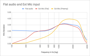
| + | I made a [https://docs.google.com/spreadsheets/d/17_wWe14px_-2LUHl6XJN6EMRTjYnuYQXnqUBVkd49vY google sheet graph of this showing the response] of the bad/good radios and the variance across the audio and RF spectrum. | ||
| + | |||
| + | There's a [https://www.youtube.com/watch?v=P3y5gdXFr_Y video here showing the rolloff] of the audio/deviation vs frequency and the response on a monitor. This seems to confirm the findings of the 3000 Hz alignment point as being invalid. | ||
| + | |||
| + | |||
| + | |||
| + | [[File:Waris UHF Flat audio and Ext Mic input (known good radio).png|thumb|center|Waris UHF Flat audio and Ext Mic input (known good radio)]] | ||
| + | |||
| + | [[File:Waris UHF Flat audio and Ext Mic input bad radio.png|thumb|center|Waris UHF Flat audio and Ext Mic input bad radio]] | ||
| + | |||
| + | [[File:Waris UHF Flat audio and Ext Mic input (fixed).png|thumb|center|Waris UHF Flat audio and Ext Mic input (fixed)]] | ||
= HT 1550 = | = HT 1550 = | ||
The HT1550 was the high end portable at the time, they can do 160 channels (of course modifiable to 255), but were VHF/UHF only. | The HT1550 was the high end portable at the time, they can do 160 channels (of course modifiable to 255), but were VHF/UHF only. | ||
| + | |||
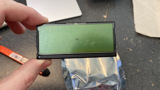
| + | ==Dot Matrix LCD Repair== | ||
| + | [[File:HT1550XLS LCD Missing Lines.jpg|99px|frameless|thumb|left|HT1550XLS LCD Missing Lines]] | ||
| + | Have missing lines on your HT1550 Dot Matrix LCD? Try this to bring your pixels back to life. | ||
| + | *[[HT1550XLS LCD Repair]] | ||
| + | It's a risky repair but can salvage an otherwise junk LCD. | ||
== Edit mode (FPP) == | == Edit mode (FPP) == | ||
| Line 438: | Line 909: | ||
| − | == Codeplug Map == | + | == Tuning and FDB Codeplug Map == |
{| class="wikitable" style="margin: 0 auto; text-align: center;" | {| class="wikitable" style="margin: 0 auto; text-align: center;" | ||
| − | |+ Waris | + | |+ Waris Tuning and FDB CP Map |
|- | |- | ||
! style="width:6.0%;"| Byte Offset | ! style="width:6.0%;"| Byte Offset | ||
| Line 523: | Line 994: | ||
| colspan="1" |[[#0x2E1 - FPP|FPP]] | | colspan="1" |[[#0x2E1 - FPP|FPP]] | ||
| colspan="1"|[[#Conventional Personalities|Conv Pers]] | | colspan="1"|[[#Conventional Personalities|Conv Pers]] | ||
| − | | colspan="1" |Unknown | + | | colspan="1" |[[#0x2E3|Unknown]] |
| style="background: orange;" colspan="1"|Checksum 9 | | style="background: orange;" colspan="1"|Checksum 9 | ||
|- | |- | ||
| Line 534: | Line 1,005: | ||
These two bytes are the length of the tuning block. Typically 0x0280 | These two bytes are the length of the tuning block. Typically 0x0280 | ||
| + | |||
| + | === RX Piers === | ||
| + | |||
| + | 0x139 - 0x146 - 7 int(16) piers | ||
| + | |||
| + | 450-527 default - 3A9D 4015 48AD 584D 61AD 697D 76BB | ||
| + | 450.025 457.025 468.025 488.025 500.025 510.025 526.975 | ||
| + | |||
| + | 440-517 mod - 32CD 3845 40DD 507D 59DD 61AD 6EEB | ||
| + | 440.025 447.025 458.025 478.025 490.025 500.025 516.975 | ||
| + | |||
| + | == TX Piers === | ||
| + | 0x147 - 0x154 - 7 int(16) piers | ||
| + | |||
| + | 450-527 default - 3A9D401548AD584D61AD6E2D76BB | ||
| + | 440-517 mod - 32CD384540DD507D59DD61AD6EEB | ||
| + | |||
| + | === Test Frequencies (RF TEST MODE) === | ||
| + | 0x1C9 - 0x1E4 - 14 int(16) piers | ||
| + | |||
| + | UHF R2 example: | ||
| + | RX 1 TX 1 RX 2 TX 2 RX 3 TX 3 RX 4 TX 4 RX 5 TX 5 RX 6 TX 6 RX 7 TX 7 | ||
| + | 3A9D 3AA2 449D 44A2 4EA2 4EA7 58A7 58B1 62B1 62B6 6CB1 6CB6 76B6 76BB | ||
| + | 450.025 450.05 462.825 462.85 475.65 475.675 488.475 488.525 501.325 501.35 514.125 514.15 526.95 526.975 | ||
| + | Mod -10 MHz - 32CD32D23CCD3CD246D246D750D750E15AE15AE664E164E66EE66EEB | ||
| + | 32CD 32D2 3CCD 3CD2 46D2 46D7 50D7 50E1 5AE1 5AE6 64E1 64E6 6EE6 6EEB | ||
| + | 440.025 440.05 452.825 452.85 465.65 465.675 478.475 478.525 491.325 491.35 504.125 504.15 516.95 516.975 | ||
=== Tuning Checksum === | === Tuning Checksum === | ||
| Line 630: | Line 1,128: | ||
22,600/200 = 116 MHz + 103 base = 216 MHz | 22,600/200 = 116 MHz + 103 base = 216 MHz | ||
| + | |||
| + | 440 MHz = 32C8 | ||
| + | |||
| + | 517 MHz = 6EF0 | ||
| + | |||
| + | 10 MHz = 7D0 (useful for subtraction) | ||
=== High Frequency === | === High Frequency === | ||
| Line 721: | Line 1,225: | ||
40 - A, 25 series only, Mobile only | 40 - A, 25 series only, Mobile only | ||
| − | |||
| − | |||
| − | + | === 0x2DE === | |
| − | |||
| − | |||
| − | |||
| − | |||
| − | |||
| − | |||
| − | |||
| − | |||
| − | |||
| − | |||
| − | |||
| − | |||
| − | |||
| − | |||
| − | |||
| − | |||
| − | |||
| − | |||
| − | |||
| − | |||
| − | |||
| − | |||
| − | |||
| − | |||
| − | |||
| − | |||
| − | |||
| − | |||
| − | |||
| − | |||
| − | |||
| − | |||
| − | |||
| − | |||
| − | |||
| − | |||
| − | |||
| − | |||
| − | |||
| − | |||
| − | |||
| − | |||
| − | |||
| − | |||
| − | |||
| − | |||
| − | |||
| − | |||
| − | |||
| − | |||
| − | |||
| − | |||
| − | |||
| − | |||
| − | |||
| − | |||
| − | |||
| − | |||
| − | |||
| − | |||
| − | |||
| − | |||
| − | |||
| − | |||
| − | |||
| − | |||
| − | |||
| − | |||
| − | |||
| − | |||
| − | |||
| − | |||
| − | |||
| − | |||
| − | |||
| − | |||
| − | |||
| − | |||
| − | |||
| − | |||
| − | |||
| − | |||
| − | |||
| − | |||
| − | |||
| − | |||
| − | |||
| − | |||
| − | |||
| − | |||
| − | |||
| − | |||
| − | |||
| − | |||
| − | |||
| − | |||
| − | |||
| − | |||
| − | |||
| − | |||
| − | |||
| − | |||
| − | |||
| − | |||
| − | |||
| − | |||
| − | |||
| − | |||
| − | |||
| − | |||
| − | |||
| − | |||
| − | |||
| − | |||
| − | |||
Looks to be a bit mask. Changing from 0xA1 to 0x81 (toggle bit 5) changed an HT to a mobile. On the mobile, squelch adjustment went away, along with radio password. | Looks to be a bit mask. Changing from 0xA1 to 0x81 (toggle bit 5) changed an HT to a mobile. On the mobile, squelch adjustment went away, along with radio password. | ||
| Line 897: | Line 1,284: | ||
Note that enabling FPP is possible in the mobile and HT1250 (even 750) radios. It will show up in the CPS, allow you to add it to the menu and everything, but it won't work. Edit mode also needs to be enabled on that channel and you need the red battery or hacked firmware. If anyone has Ideas for the CDM, let me know. | Note that enabling FPP is possible in the mobile and HT1250 (even 750) radios. It will show up in the CPS, allow you to add it to the menu and everything, but it won't work. Edit mode also needs to be enabled on that channel and you need the red battery or hacked firmware. If anyone has Ideas for the CDM, let me know. | ||
| + | |||
| + | === 0x2E3 === | ||
| + | Unsure what this is, but when opening an srecord and saving it again, CPS changed this from from 0x30 to 0x10 (and low power from 0x16 to 0x19). | ||
| + | |||
| + | == [[Waris_Programing_Block|Programing block]] == | ||
| + | |||
| + | This now has it's own page | ||
| + | |||
| + | The programing block is the next block after the tuning and FDB blocks, typically starting at 0x300. | ||
| + | |||
| + | = CodePlug Backup = | ||
| + | |||
| + | It's vital you backup your full codeplug (tuning, features and programing) before you try anything. | ||
| + | |||
| + | You use [[Waris#CP Tool|CPtool to do this]] and read the radio from 0x0000 to 0x3FFF (16k bytes of eeprom). | ||
| + | |||
| + | This will make a .mot file which is the binary version of your code plug. No matter what you do to the radio, you can always recover it using this file and a flash file if need be. | ||
= Flashing = | = Flashing = | ||
| Line 925: | Line 1,329: | ||
These are text files of the binary firmware in [https://en.wikipedia.org/wiki/SREC_(file_format) S-record] format. The only difference is the header must be removed. The file name must be *.0 as well, and it cannot be loaded via a network filesystem path. | These are text files of the binary firmware in [https://en.wikipedia.org/wiki/SREC_(file_format) S-record] format. The only difference is the header must be removed. The file name must be *.0 as well, and it cannot be loaded via a network filesystem path. | ||
| + | |||
| + | == HT750 to HT1250 Conversion == | ||
| + | From [https://wiki.w3axl.com W3AXL] | ||
| + | === Required Parts === | ||
| + | * Working HT750 in your bandsplit of choice (make sure to get a 16-channel model, otherwise you'll have to replace the channel knob with a 16-position encoder as the 4-channel models have hard stops) | ||
| + | * Donor HT1250 housing, lcd, keypad, and assorted housing parts & flexes. You can get new grey-market housing kits with all needed parts from the usual suspects online. [https://www.ebay.com/usr/2013lin-wang lindawang] on eBay is a known source. | ||
| + | * Programming Cable | ||
| + | |||
| + | === High-level procedure === | ||
| + | # Replace the HT750 housing with the HT1250 housing and power up the radio. You should see the battery, clock, and RSSI icons show up. This tells you everything is working. | ||
| + | # [[Waris#CodePlug Backup|Backup your codeplug!]] | ||
| + | # Find the default codeplug from the [[Waris#Binary Codeplugs|Waris binary codeplugs tar.gz archive]] that reflects the radio you'll be converting to. You'll want to find the HT1250 model number you need for your specific band/control combo, and try to get the Tanapa number as close as possible (i.e. similar pattern - I was able to get a PMUD1481A codeplug to work in an HT750 with Tanapa PMUD1573A) | ||
| + | # Edit the serial number and any other features you'd like based on the [[Waris#Editing the Codeplug|procedure explained above]], making sure your checksums are correct | ||
| + | # Write this new binary file to the radio using CPTool | ||
| + | # If the radio boots up normally, congrats! You did something right. If you get an error, you probably messed up the checksums or used an invalid feature code somewhere. | ||
| + | # Write the tuning data back to the radio from your original codeplug backup using CPTool and the ranges 0x0000 to 0x0280 | ||
| + | # At this point you should have a fully working HT1250, minus the RTC functionality. Theoretically you could add the parts to get a working clock, but I haven't tried it yet. | ||
= Software & Docs = | = Software & Docs = | ||
| Line 930: | Line 1,351: | ||
== Docs == | == Docs == | ||
| − | [[ | + | [[Media:HT1250LS+ 220 700MHz Service Manual.PDF|220 700MHz Service Manual.PDF]] |
| − | [[ | + | [[Media:Basic Service Manual HT1250•LS+ 200 MHz 700 MHz 6864110R15-O.pdf|Basic Service Manual HT1250•LS+ 200 MHz 700 MHz 6864110R15-O]] |
| + | [[Media:Detailed Service Manual HT1250•LS+ 200 MHz 700 MHz 6864110R12-O.pdf|Detailed Service Manual HT1250•LS+ 200 MHz 700 MHz 6864110R12-O]] | ||
| − | [[ | + | [[Media:CDM1550 200-700 Mhz detailed service manual.pdf|CDM1550 200-700 Mhz detailed service manual]] |
| − | [[ | + | [[Media:6881088C46 Motorola HT MTX PRO Detailed Service Manual.pdf|6881088C46 Motorola HT/MTX/PRO Detailed Service Manual]] |
| − | [[ | + | [[Media:68P80906Z54-D Motorola HT MTX PRO Basic Service Manual.pdf|68P80906Z54-D Motorola HT/MTX/PRO Basic Service Manual]] |
| − | [[ | + | [[Media:6866577D06-A Motorola GP Professional Basic Service Manual.pdf|thumb|6866577D06-A Motorola GP Professional Basic Service Manual]] |
| − | [[ | + | [[Media:6866558D04-O Motorola professional GP series including 300R1 Detailed Service Manual.pdf|6866558D04-O Motorola professional GP series including 300R1 Detailed Service Manual]] -- Note this has shit formatting from some gay ass manual site that fucked up the page sizes. Unless you need 300 MHz stuff, use the one below. |
| − | [[ | + | [[Media:6866558D03-P Motorola GP Series Detailed Service Manual - Proper Paper Size.pdf|6866558D03-P Motorola GP Series Detailed Service Manual - Proper Paper Size]] Use this one unless you need 300 MHz |
[[media:RLN4780 4 line remote mount kit with speaker manual.pdf|RLN4780 4 line remote mount kit with speaker manual]] - This is the remote mount 4 page manual for the GM380/1280 and MTM700 | [[media:RLN4780 4 line remote mount kit with speaker manual.pdf|RLN4780 4 line remote mount kit with speaker manual]] - This is the remote mount 4 page manual for the GM380/1280 and MTM700 | ||
| + | |||
| + | [[Media:Product Comparison Analog Portables.pdf|Product Comparison Analog Portables]] | ||
| + | |||
| + | [[Media:HT1250ls Radio User Guide 6881088C42-G.pdf|HT1250ls Radio User Guide 6881088C42-G]] | ||
| + | |||
| + | [[Media:Final Reflashing Instructions Portable Only-5-29-02.pdf|Final Reflashing Instructions Portable Only-5-29-02]] | ||
| + | |||
| + | ==== CP125/CP150/CP200 ==== | ||
| + | |||
| + | [[Media:CP125 Portable Two-Way Radio User Guide 6881098C60-O.pdf|CP125 Portable Two-Way Radio User Guide 6881098C60-O]] | ||
| + | |||
| + | [[Media:CP125 Service Manual 6881096C38-B.pdf|CP125 Service Manual 6881096C38-B]] | ||
| + | |||
| + | |||
| + | [[Media:CP150 CP200 Commercial Series Two-Way Radio User Guide 6880309N60.pdf|CP150 CP200 Commercial Series Two-Way Radio User Guide 6880309N60]] | ||
| + | |||
| + | [[Media:CP150 CP200 Commercial Series Two-Way Radio User Guide 6880309N60-A.pdf|CP150 CP200 Commercial Series Two-Way Radio User Guide 6880309N60-A]] | ||
| + | |||
| + | [[Media:CP150 CP200 Basic Service Manual 6880309N61-B.pdf|CP150 CP200 Basic Service Manual 6880309N61-B]] | ||
| + | |||
| + | [[Media:CP150 CP200 Detailed Service Manual 6880309N62-C.pdf|CP150 CP200 Detailed Service Manual 6880309N62-C]] | ||
| + | |||
| + | [[Media:CP150 CP200 Detailed Service Manual 6880309N62-D.pdf|CP150 CP200 Detailed Service Manual 6880309N62-D]] | ||
| + | |||
| + | [[Media:CP200XLS Basic Service Manual 68009328001-A.pdf|CP200XLS Basic Service Manual 68009328001-A]] | ||
| + | |||
| + | [[Media:CP185 Basic Service Manual 68007024004-D.pdf|CP185 Basic Service Manual 68007024004-D]] | ||
| + | |||
| + | [[Media:PR860 User Guide 6881098C02-P.pdf|PR860 User Guide 6881098C02-P]] | ||
| + | |||
| + | [[Media:PR860 Basic Service Manual 6881098C42-P.pdf|PR860 Basic Service Manual 6881098C42-P]] | ||
| + | |||
| + | [[Media:PR860 Detailed Service Manual 6881098C43-P.pdf|PR860 Detailed Service Manual 6881098C43-P]] | ||
| + | |||
| + | |||
| + | ==== Expert Series (EX600) ==== | ||
| + | |||
| + | [[Media:EX500 Users Guide 6881093C98-C.pdf|EX500 Users Guide 6881093C98-C]] | ||
| + | |||
| + | [[Media:EX600 User Guide 68P81094C70-O.pdf|EX600 User Guide 68P81094C70-O]] | ||
| + | |||
| + | [[Media:EX600•XLS Expert Series Two-Way Radio User Guide 68P81095C10-O.pdf|EX600•XLS Expert Series Two-Way Radio User Guide 68P81095C10-O]] | ||
| + | |||
| + | [[Media:EX500 EX600 EX600•XLS Expert Series Two-Way Radio Basic Service Manual 68P81094C00-B.pdf|EX500 EX600 EX600•XLS Expert Series Two-Way Radio Basic Service Manual 68P81094C00-B]] | ||
| + | |||
| + | [[Media:EX500 EX600 EX560XLS EX600XLS Basic Service Manual 6881094C00-C.pdf|EX500 EX600 EX560XLS EX600XLS Basic Service Manual 6881094C00-C]] | ||
| + | |||
| + | [[Media:Elite Series Detailed Service Manual 6881094C21-A.pdf|Elite Series Detailed Service Manual 6881094C21-A]] | ||
| + | |||
| + | [[Media:MANUAL REVISION FMR-2027-1 EX500 EX600 EX600•XLS Detailed Service Manual 6881094C21-A.pdf|MANUAL REVISION FMR-2027-1 EX500/EX600/EX600•XLS Detailed Service Manual 6881094C21-A]] | ||
| + | |||
| + | [[Media:PRO Series Elite Detailed Service Manual 6881094C21-B.pdf|PRO Series Elite Detailed Service Manual 6881094C21-B]] | ||
| + | |||
| + | === Release Notes === | ||
| + | |||
| + | ==== Professional CPS ==== | ||
| + | |||
| + | [[Media:ProSeries CPS R06.11.05 Notes.pdf|ProSeries CPS R06.11.05 Notes]] | ||
| + | |||
| + | [[Media:ProSeries CPS R06.11.07 Notes.pdf|ProSeries CPS R06.11.07 Notes]] | ||
| + | |||
| + | [[Media:ProSeries CPS R06.11.10 Notes.pdf|ProSeries CPS R06.11.10 Notes]] | ||
| + | |||
| + | [[Media:ProSeries CPS R06.12.02 Notes v4.pdf|ProSeries CPS R06.12.02 Notes v4]] | ||
| + | |||
| + | [[Media:ProSeries CPS R06.12.04 Notes.pdf|ProSeries CPS R06.12.04 Notes]] | ||
| + | |||
| + | [[Media:ProSeries CPS R06.12.05 Notes.pdf|ProSeries CPS R06.12.05 Notes]] | ||
| + | |||
| + | [[Media:ProSeries CPS R06.12.08 Release Notes.pdf|ProSeries CPS R06.12.08 Release Notes]] | ||
| + | |||
| + | [[Media:ProSeries CPS R06.12.09 Notes.pdf|ProSeries CPS R06.12.09 Notes]] | ||
| + | |||
| + | ==== Professional Mobile Firmware ==== | ||
| + | |||
| + | [[Media:ProSeries Mobile R05.05.17 Notes.pdf|ProSeries Mobile R05.05.17 Notes]] | ||
| + | |||
| + | [[Media:ProSeries Mobile R05.05.19 Notes.pdf|ProSeries Mobile R05.05.19 Notes]] | ||
| + | |||
| + | [[Media:ProSeries Mobile R05.08.01 Notes.pdf|ProSeries Mobile R05.08.01 Notes]] | ||
| + | |||
| + | [[Media:ProSeries Mobile R05.08.05 Notes.pdf|ProSeries Mobile R05.08.05 Notes]] | ||
| + | |||
| + | [[Media:Professional Series Mobile R05.08.05 Notes.pdf|Professional Series Mobile R05.08.05 Notes]] | ||
| + | |||
| + | [[Media:ProSeries Mobile R05.09.01 Notes.pdf|ProSeries Mobile R05.09.01 Notes]] | ||
| + | |||
| + | [[Media:ProSeries Mobile R05.10.01 Notes v.4.pdf|ProSeries Mobile R05.10.01 Notes v.4]] | ||
| + | |||
| + | [[Media:ProSeries Mobile R05.10.02 Notes.pdf|ProSeries Mobile R05.10.02 Notes]] | ||
| + | |||
| + | [[Media:ProSeries Mobile R05.10.03 Notes.pdf|ProSeries Mobile R05.10.03 Notes]] | ||
| + | |||
| + | [[Media:ProSeries Mobile R05.10.04 Notes.pdf|ProSeries Mobile R05.10.04 Notes]] | ||
| + | |||
| + | ==== Professional Portable Non-4 Line Display Firmware ==== | ||
| + | |||
| + | [[Media:ProSeries Portable R05.09.11 Notes.pdf|ProSeries Portable R05.09.11 Notes]] | ||
| + | |||
| + | [[Media:ProSeries Portable R05.10.05 non4line Notes.pdf|ProSeries Portable R05.10.05 non4line Notes]] | ||
| + | |||
| + | [[Media:ProSeries Portable R05.13.09 non4line Notes.pdf|ProSeries Portable R05.13.09 non4line Notes]] | ||
| + | |||
| + | [[Media:ProSeries Portable R05.14.03 non4line Notes.pdf|ProSeries Portable R05.14.03 non4line Notes]] | ||
| + | |||
| + | [[Media:ProSeries Portable R05.17.01 non4line Notes v4.pdf|ProSeries Portable R05.17.01 non4line Notes v4]] | ||
| + | |||
| + | [[Media:ProSeries Portable R05.17.02 non4line Notes.pdf|ProSeries Portable R05.17.02 non4line Notes]] | ||
| + | |||
| + | [[Media:ProSeries Portable R05.18.00 non4line Notes.pdf|ProSeries Portable R05.18.00 non4line Notes]] | ||
| + | |||
| + | [[Media:ProSeries Portable R05.18.01 non4line Notes.pdf|ProSeries Portable R05.18.01 non4line Notes]] | ||
| + | |||
| + | ==== Professional Portable 4 Line Display Firmware ==== | ||
| + | |||
| + | [[Media:ProSeries Portable R05.10.05 4line Notes.pdf|ProSeries Portable R05.10.05 4line Notes]] | ||
| + | |||
| + | [[Media:ProSeries Portable R05.13.09 4line Notes.pdf|ProSeries Portable R05.13.09 4line Notes]] | ||
| + | |||
| + | [[Media:ProSeries Portable R05.14.03 4line Notes.pdf|ProSeries Portable R05.14.03 4line Notes]] | ||
| + | |||
| + | [[Media:ProSeries Portable R05.16.01 4line Notes.pdf|ProSeries Portable R05.16.01 4line Notes]] | ||
| + | |||
| + | [[Media:ProSeries Portable R05.17.01 4line Notes v4.pdf|ProSeries Portable R05.17.01 4line Notes v4]] | ||
| + | |||
| + | [[Media:ProSeries Portable R05.17.02 4line Notes.pdf|ProSeries Portable R05.17.02 4line Notes]] | ||
| + | |||
| + | [[Media:ProSeries Portable R05.18.00 4line Notes.pdf|ProSeries Portable R05.18.00 4line Notes]] | ||
| + | |||
| + | [[Media:ProSeries Portable R05.18.01 4line Notes.pdf|ProSeries Portable R05.18.01 4line Notes]] | ||
| + | |||
| + | ==== MTX CPS ==== | ||
| + | |||
| + | [[Media:PrivacyPlus Portable R01.03.73 Release Notes.pdf|PrivacyPlus Portable R01.03.73 Release Notes]] | ||
| + | |||
| + | [[Media:PrivacyPlus Portable R01.04.01 Release Notes.pdf|PrivacyPlus Portable R01.04.01 Release Notes]] | ||
| + | |||
| + | [[Media:PrivacyPlus Portable R01.04.03 Release Notes.pdf|PrivacyPlus Portable R01.04.03 Release Notes]] | ||
| + | |||
| + | [[Media:PrivacyPlus CPS R02.00.02 Release Notes.pdf|PrivacyPlus CPS R02.00.02 Release Notes]] | ||
| + | |||
| + | [[Media:PrivacyPlus CPS R02.01.03 Release Notes.pdf|PrivacyPlus CPS R02.01.03 Release Notes]] | ||
| + | |||
| + | [[Media:PrivacyPlus CPS R02.03.00 Release Notes.pdf|PrivacyPlus CPS R02.03.00 Release Notes]] | ||
== CPS == | == CPS == | ||
| − | [[ | + | [[Media:Professional CPS R.06.12.09 AA.zip|Professional CPS R.06.12.09 AA.zip]] - Latest CPS Release as of 12/14/2016 |
| − | [[ | + | [[Media:Global Tuner R 02.18.00.zip|Global Tuner R 02.18.00.zip]] - Latest Tuner Release as of 12/14/2016 |
| − | [[ | + | [[Media:HVN9025 v6.12.05.zip|Waris CPS 6.12.05]] Waris CPS 6.12.05 |
| − | [[ | + | [[Media:R02.02.00 Waris Tuner.zip|Waris Tuner 2.02]] Waris Tuner 2.02 |
| + | |||
| + | [[Media:PrivacyPlus Portable CPS R01.04.03.exe|PrivacyPlus Portable CPS R01.04.03]] - for the MTX150, MTX1500, MTX450, MTX4500, MTX850, MTX8250, MTX950, MTX9250 | ||
| + | |||
| + | [[Media:PrivacyPlus CPS R02.03.00.zip|PrivacyPlus CPS R02.03.00]] - for the MTX150, MTX1500, MTX450, MTX4500, MTX850, MTX8250, MTX950, MTX9250 | ||
| + | |||
| + | ::'''These are for the EU Waris radios''' | ||
| + | |||
| + | [[Media:Professional GP300 GM300 Series CPS R03.11.16 ENVN400Z.zip|Professional GP300/GM300 Series CPS R03.11.16 ENVN400Z]] | ||
| + | |||
| + | [[Media:MPT CPS R00.02.14 EMEA ENVN4006H.zip|MPT CPS R00.02.14 EMEA ENVN4006H]] | ||
== Firmware Upgrades == | == Firmware Upgrades == | ||
| Line 980: | Line 1,556: | ||
== Unofficial software == | == Unofficial software == | ||
[[File:Waris Codeplugtool.zip| cptool allows writing and reading raw codeplug from a radio.]] allows writing and reading raw codeplug from a radio. | [[File:Waris Codeplugtool.zip| cptool allows writing and reading raw codeplug from a radio.]] allows writing and reading raw codeplug from a radio. | ||
| + | |||
| + | === CP Tool === | ||
| + | It's important when reading a codeplug from a tool using Codeplug Tool you must read the radio from 0x0000-3FFF the 16kbytes. By default it only reads 0x0000-03FF or the first 1024 bytes. If you want to make a complete backup you need the entire code plug. | ||
| + | |||
| + | [[File:Waris Codeplug tool reading 16k byte codeplug.png|thumb|center|Waris Codeplug tool reading 16k byte codeplug]] | ||
[[File:Unofficial Global Tuner R02.16.05.zip|Hacked global tuner for editing the serial number]] Hacked global tuner for editing the serial number | [[File:Unofficial Global Tuner R02.16.05.zip|Hacked global tuner for editing the serial number]] Hacked global tuner for editing the serial number | ||
| Line 992: | Line 1,573: | ||
[[File:FW-Mobile-R05.10.04.bin|thumb|US Waris Mobile Firmware R05.10.04 Final Version]] The binary of R05.10.04 last version of firmware for the CDM | [[File:FW-Mobile-R05.10.04.bin|thumb|US Waris Mobile Firmware R05.10.04 Final Version]] The binary of R05.10.04 last version of firmware for the CDM | ||
| + | |||
| + | [[Media:CDM Model Number Recovery Kit.zip|CDM Model Number Recovery Kit]] | ||
| + | |||
| + | [[Media:EU waris lab upgradekit r02.05.01.zip|EU waris lab upgrade kit R02.05.01]] | ||
| + | |||
| + | [[Media:EU Waris LabUpgradekit R03.07.00.zip|EU Waris LabUpgradekit R03.07.00]] | ||
| + | |||
| + | [[media:EU Waris Lab Upgradekit - R03.10.02 EN.zip|EU Waris LabUpgradekit - R03.10.02]] | ||
== Utilities == | == Utilities == | ||
Latest revision as of 14:32, 27 February 2022
Contents
- 1 Waris
- 2 Programming and Flash Cables
- 3 Cables
- 4 220 HT1250ls and CDM 1550ls
- 5 Mobile Power Amp
- 6 UHF 450-527 Ham Band Mod
- 7 CDM Low Band Range 3 to 46-54 MHz
- 8 Audio Balance
- 9 HT 1550
- 10 Code Plug Map
- 10.1 passwords
- 10.2 Tuning and FDB Codeplug Map
- 10.3 TX Piers =
- 10.3.1 Test Frequencies (RF TEST MODE)
- 10.3.2 Tuning Checksum
- 10.3.3 Feature Length
- 10.3.4 Block Header
- 10.3.5 Serial Number
- 10.3.6 Model Number
- 10.3.7 Codeplug Version
- 10.3.8 Programing Source
- 10.3.9 Programing Date
- 10.3.10 Channel Step
- 10.3.11 Base Frequency
- 10.3.12 Low Frequency
- 10.3.13 High Frequency
- 10.3.14 Code Plug Part Number
- 10.3.15 TANAPA
- 10.3.16 Power
- 10.3.17 Region
- 10.3.18 0x2DD - CHD
- 10.3.19 0x2DE
- 10.3.20 Bit 5 on makes a mobile
- 10.3.21 2E0:1
- 10.3.22 0x2E0
- 10.3.23 0x2E1 - FPP
- 10.3.24 0x2E3
- 10.4 Programing block
- 11 CodePlug Backup
- 12 Flashing
- 13 Software & Docs
Waris
This was originally put together when I got into the HT1250 200 MHz radios. They modified ok, but the way of doing it as suggested left much to be desired, and the DTMF pad didn't work and the radios were narrow band only.
Over time, I've gotten more into these with the CDM1250/1550 and other waris series radios. I've not seen any of the European ones, but I've been working with the US versions for FM service in ham radio.
What I've found is the radios features are determined by the "codeplug" settings. This is simply a packed (hex) data written into the eeprom chip of the radio containing tuning, feature and programing data. This is the same area the programing data from CPS is written in, but CPS is unable to change it. The majority of modification of these radios to amateur service is done with modifications to the codeplug. The codeplug layout appears to be the same for most US versions of the radios, but there are some which are different.
The cool things about these radios is any of the limited ones can be "changed" into the highend, or even more.
Every Waris radio can do the following:
- 255 personalities only limited by the 16kb of eeprom space. If you load up a bunch of MDC and other crap, CPS will limit adding new channels.
- MDC/QCII/DTMF signaling
- LTR trunking
- Passport (with the right board)
- 4line portables can be flashed to do FPP/edit mode without special battery
- Flexibility of band edges when re-aligned properly
- it is impossible to "brick" a radio. You can fuck it up so it won't boot, but it can be recovered.
- ability to flash the firmware between EU Select 5 calling and US MDC models (not done too much on this) Even MPT should be possible.
- mobiles will support any control head, even the 4 line display from the GM380/1280.
Types of Radios
Radios are selected by model and the radio assembly is called a Tanapa/TANAPA[1]. The board Tanapa can be different and is what is in the codeplug FDB.
Tanapa is a Japanese term But a Motorola adopted the word from the Japanese manufacturing industry meaning Kit or Partial Assembly What happens during the manufacturing process, the Tanapa is assigned to items like a Frame or Partial item number. As it goes through the Build process, it will finally become a Radio, ( or completed accessory ) and thus a Model / Serial Number ( or Part Number ) will be assigned when completed.[1]
Hence, one will see Tanapa on all kinds of Motorola items Boards , Completed Radios, Frames, Kits, Labels, etc.
I have a list of all US Model numbers, Tanapa's, features and codeplug versions
HT's
HT750 - No Display, 4 or 16 channels
HT1250 - One line display, multiple channels up to 128
HT1250ls - limited version of the HT1250, normally missing MDC on conventional
HT1250 UHF1 PMUE1711B Pictures of a UHF R1 HT1250 with all shields removed.
HT1550xls - 4 line display radio, 160 channels, VHF/UHF only
EX500 - No display, smaller submersible radio, 16 channels
EX560xls - one line, smaller submersible radio,
EX600 - one line
EX600xls - one line, 160 channels
CP200 - no display, 4/16 channels
CP200xls -
PR400 - VHF 1/VHF 2, UHF 1/UHF 2/UHF 3 - comes in 16, 32 or, 64 channels
GP series from EMEA
These have EMEA (Latin America/export) versions known as GP
GP340 - HT750
Note I got a GP340 in LB2 when I was in Germany. As they use the euro CPS for 5 tone I wanted to get it going as a US version with MDC and newer firmware. The 5 tone HT's all use 512k flash memory, not the 128k of the HT750/1250 (1550 is 512k), and I was able to flash it using the unofficial kit, then put a default codeplug in it. It took me trying a couple default codeplugs to find one that works. After this I flashed it to R05.18.01 using the normal tools.
What might be interesting would being able to convert the LB GP340 to HT1550 as the GP's all have the 512k Flash ram. A default code plug would need to be edited from an HT1550 for low-band. Theoretically this should work, the parts line up.
GP344 - EX500
GP360 - HT1250
GP366 - EX560xls
GP380 - HT1250
GP580 - HT1250 ls?
GP680 - MPT 1250
GP1280 - MPT 1550
Mobiles
CDM/PRO US/CALA/APAC MDC
These are the series most people see here in the USA. They will do analog voice and come in many different models determined by the control head.
There is no N head for these.
GM EMEA 5-Tone/MPT1327
These are 5 Tone or MPT radios and come in different models, determined by the control head.
GM140/GM340/GM640 - C control head GM160/GM360/GM660 - F control head GM380/GM1280 - N control head (4 line)
MTM700 TETRA
This is not really a waris radio, but the build is similar. These are tetra models for the EU market.
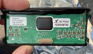
The 4 line control head on this will work on the Waris radios, but the fixed icons for the LCD are different. It may be possiable to replace the LCD module in this control head with the GM380 control head module (P/N 5164313B02) and get it back. I've found this doesn't really effect function, but the talkaround/scan/etc indicators are way different in the TETRA radio.
Control Heads
It's possible to put a 4 line control head on a Waris mobile. This can be the control head from the MTM700 as well, but the LCD ICONS will be different.
Why do you want to?
- Enables you to control VOX status from the control head
- Shows the frequency and PL/DPL tone on the display
- You need another clock to set
- You get to be cool
4 Line Display Use
First ensure your display works before going further. If it's the MTM700 LCD or Display module, the Icons will be different, scan will show up as a period on it for example. The keys will be different and the Menu key can be especially confusing.
- Check your codeplug
- is the existing codeplug a Major version 3? Does it have an FDB2 size of 0x09? If not, you'll have to get a binary codeplug and push it into the radio that is
- This is done by selecting a default codeplug that matches your needs closely. I find a code plug that has analog only, no LTR and the options I need. Then I edit this codeplug in a hex editor and paste it from 0x280 to the end into the existing codeplug. Using the tools to convert this to an srec file makes it easy to open in CPS with out needing to write it to a radio.
- once this is working how you like it, program it into the radio using Codeplug tool.
- connect up your control head and enjoy!
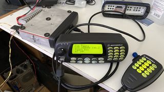
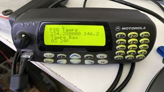
Remote mount works with the 4 line head too. I've taken to calling this a CDM1850 :)
Low Band 4 Line Display
I did some work recently on these for low band. Note that lowband didn't have any default codeplugs for the 4 line, N, display.
I have made the following codeplugs for lowband with these features:
- 42-54 MHz
- Tuning and test frequencies corrected
- Region 1
- Blank Serial
- AA only, no trunking
- QCII, MDC, and DTMF signaling enbled
- 52.525 Channel 1
There is a binary file and an srecord that can be opened in CPS.
Note that if you want to use this Binary file and have the tuning piers set, you'll need to retune the radio. The other option is to take your tuning data and modify it. This can be done via waris.py or by using the data below
At offset 0x139 replace the tuning piers:
112D122513291469158115F91789112D122513291469158115F91789
with
112B12BB145515E9177E19131AA8112B12BB145515E9177E19131AA8

At offset 0x1C8 replace the test channels:
1135113a1225121113291315146914551581156d15f915e51766176b
with
1135113912BB12A71455144015E915D5177E176A191318FF1A851A8A

If using waris.py set the tuning channels as follows for RX and TX 1-7
41.975 43.975 46.025 48.050 50.075 52.100 54.125

The Test Channels are
  TX     RX
42.025 42.050
43.975 43.875
46.025 45.925
48.050 47.950
50.075	49.975
52.100 52.000
53.950 53.975
To use these files, decide how you want to do it, ie preserve your tuning data or not. As you're moving the tuning piers, you have to retune anyways, so I would use Codeplug tool and write the entire binary codeplug in, then retune. However many people don't want to do this, and you can just merge your radio, and write it from 0x280-end, preserving the tuning area.
42-54mhz-1850 Default Srecord Format.srec - 42-54mhz CDM 1850 Default Codeplug in Srecord Format
This is based on a M25DKF9AA5A model, IMUB6002A Tanapa, a low band 3 conventional radio.
42-54mhz-1850 Default Binary Format.bin - 42-54mhz CDM 1850 Default Codeplug in Binary Format
If you want to write the codeplug into your radio
Option boards
Option boards are the keypad in the HT1250, and can be installed in the CDM mobile radios as well.
Known boards are below:
AAHLN9725C - Voice Storage Option board
AAHLN9729C - DTMF decode board
AAENLN4150A - Mandown board
The Mandown Option Board is compatible with all 5-Tone, MPT and MDC/Conv portable radios of the Professional Radio Series in all bands (except P040/P080 and GP320).
It is also operational with all connected original Motorola accessories for the GP Professional Radios Series portables.
Installation in any Intrinsically Safe (IS) radios will invalidate the radio’s IS approval (i.e. FM-radios).
Mandown Option Board ENLN4150A Study Guide 68P64121B10 Manual
WARIS Mandown OSS R01.01.01 2001-01-11 Programing Software - Mandown Option Board Service Software
Passport board - PTCB
The Passport Board was used in both HTs and Mobiles. Most (all?) 200 MHz radios will have them. It can be removed from the mobile and disabled if desired.
Removal is simple, just open it and remove it. I save the flex cables as they make great replacements in the HTs
Software
Passport uses it own firmware and CPS to program the PTCB. There is a complex interaction of programing of the option board and the radio it self.
Passport Docs
PassPort Data Configuration Guide
PassPort Software Compatibility
THEORY OF OPERATION: PASSPORT SITE SEARCH
PassPort CPS R03.02.00 Programming Hints
Release Notes
PassPort Firmware R06.02.13 - Release Notes 122002
PassPort Firmware R06.02.14 - Release Notes 042003
PassPort Firmware R06.02.16 Customer Release Notes
PassPort Firmware R06.02.16 - Release Notes
PassPort Firmware R07.01.11 - Release Notes 112003
PassPort Firmware R07.01.19 Release Notes
PassPort Firmware R07.02.09 Release Notes
PassPort Firmware R08.02.05 Release Notes
PassPort Firmware R08.02.06 Release Notes
PassPort Firmware R08.02.07 Release Notes
PassPort Firmware R08.00.17 Release Notes
- Service pack
PassPort Firmware R06.02.13 ServicePak - Release Notes 122002
PassPort Firmware R06.02.14 ServicePak - Release Notes 042003
PassPort R06.02.16 ServicePak - Release Notes
PassPort CPS R03.02.00 Customer Release Notes
PassPort CPS R04.00.00 - Release Notes
PassPort CPS R05.00.10 Release Notes
PassPort CPS R05.00.14 Release Notes
Unknown Boards
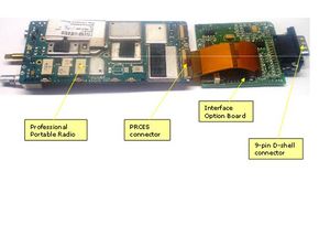
There was an API/developers guide a company could license from Motorola. Several companies made add ons for these, but I have very little information on them. I belive this is known as "Professional Radio Option Interface Specifications" or PROIS. Rotronix Ltd. was a company known to make a controller for this.
There is a manual "Motorola PROIS v2.03 Manual" which is mentioned in the LC828 manual. A copy of this would be awesome to have. This may have a part number 1202899J28
Here is a picture of one with a DB-9 connector on it. Any information on these would be appreciated.
Rotronix Ltd. made the LC828 which was a special radio based on a PROIS board and a waris radio.
https://web.archive.org/web/20130207012450/http://rotronix.co.nz/Mobile_radio_PROIS_interface.aspx
LC828 radio mods - modification to a HT750/1250 needed to make a LC828
LC828 interface manual - This has a complete document on the "Motorola Professional Portable Radio Interface Option Board(IOB) Manual". It includes a schematic of the board and parts list as well. This is the same board used in all the interfaces.
Computer controlled Radio Interface - CCRI - This is the Manual to the CCRI interface spoken by the Rotronix PROIS board. The mnaul says this is based on the CCRI protocol by T.L. Parker Ltd.
Here is a comment posted by the developer of this board on batlabs forum
Common Parts
The majority of the Waris radios, HT and Mobile are basically the same design. There are number of common parts between them and the custom chips are shared
- ASFIC - This is a custom part that generates CPU clock, filters audio (TX/RX), controls parts of the radio (VCO/PA/etc) and does the PL/DPL and signaling. It's early similar to a CML7041, both are 48 pin QFP's
Programming and Flash Cables
The CDM and HT series are programmed using windows based CPS. A rs-232 level converter is needed to talk to the radio, and in the OEM Motorola soultion consists of a Programming Test cable (AARKN4083/AARKN4074), a RIB (level converter) and a test box (RLN4460A/B).
<#gallery of shti>
The HT series program and flash via the 13 pin accessory port. The CDM mobiles program and flash via the back 20 pin accessory port or via the front RJ-50 (10 pin) connector. The font connector presents some issues when programming and flashing a unit with a remote head, and the rear connector should be used for that.
The CDM accessory cable connector is a TE AMP connector, Digi-key part number 104422-2-ND, and uses Digi-Key Part number A25989-ND for the pins.
Notes on the RIB based Cables
You should not use a RIB to Flash the radio at anything other than 9600 bps. Even then I've run into issues with this setup. Programing works well though.
A very strange issue popped up using the built in serial port on the Dell Latitude D830 with docking station. When using the docking station serial port the radio will "lock-up" and require the cable to be disconnected to be programed.
I've found the Prolific and FTDI serial adapters to work fine with the RIB for flashing/cptool. However the Prolific adapters have an issue in CPS unless they run the right version of the driver, 2.0.2.5.
File:Prolific USB-to-Serial Comm Port 2303 VER 2.0.2.5 del 17-04-2006 OK.zip
Notes on RIB-less Cables
RIB-less cables are the preferred way to work with the radio. These can be either serial or USB based. In the USB case it's simply a FTDI or Prolific serial port with a level converter.
I've used the following cables for programming
- 2 in 1 prolific cable for Waris and CDM
- Valley Enterprises® 5 in 1 FTDI USB Programming Cable Motorola Mobile and Portables
Flash Modification
I've modified my 5-in-1 Valley Cable with switches on the side and an extra pin on the boot contact to enable flashing the EX and HT/Pro line of radios.
I used the following parts from Digi-Key to do this
- 450-1635-ND - Slide Switch
- 952-3135-1-ND - Contact Spring (POGO pin)
You'll need to drill out the right part of the pcb on the connector and epoxy the switch in place, but it's very continent to have it in place.
Be sure you use the proper drivers if using the prolific cable.
Flashing and Flash adapters
If you want to flash the radio you need to put it in bootstrap mode. This is done using a flash adapter that puts the CPU (68HC11) into a special mode. The flash program loads a boot loader/flash application via the serial port and then writes the new image to flash chip.
The US Waris unofficial upgrade kit is something that was built by possibly a internal Motorola programmer, or a hack based off the official upgrade kit. Using this tool you can load any of the images on any radio, but you must ensure the image selected is the same size as the flash chip. Note this tool requires all images and default codeplugs as srecord format.
The official upgrade kit includes default codeplugs, firmware images and boot images. These are in an encrypted format, and it appears the unofficial kit has decoded these as the included codeplugs/firmware.
The official kit does this:
- Reads the codeplug and firmware info (at 9600 BPS)
- determines if it can upgrade based of #1
- puts it bootstrap mode
- loads the boot helper program via serial (at 2211 BPS)
- Boothelper runs from 0x0080 and erases the flash
- updater loads the firmware image at the baud rate set by the boot helper program
- updated then pushes the codeplug in at this baud rate too.
Note that the FL0 CPU needs the data sent at 2211 BPS, but the computer can only write at 2400 bps. This is 8% too fast. This 2x the rated baud speed difference from the 68HC11 reference manual!
For 8-bit data format, the baud-rate variation that can be tolerated is about ±4.5 percent; for 9-bit data format, the variation is about ±4 percent. This analysis assumes one of the devices was operating at the exact baud-rate frequency, and the calculations show how much the other device could vary from this. One device operating four percent too slow cannot communicate with another device operating 4 percent too fast.
What this means is if your computer's async port is running just a bit faster (RS232 gives a 3.5% error as acceptable for baud rate), the error can be too much for the radio and it will fail to load the boot helper code and thus won't flash.
Cables
CDM Accessory Connector
The CDM750/CDM1250/CDM1550/Pro Mobile pinout for the accessory connector is below.
Note that is uses Motorola's pinout for the connector which is designed to retain compatibility with the prior (Radius) radios.
| CDM Accessory Port Pin Out | ||
|---|---|---|
| Function | Pin | Notes |
| Speaker - | 1 | This is a floating output, don't connect to ground. |
| External Mic | 2 | This is controlled by the settings in the personality for emphasis, high-pass filtered |
| Digital In 1 (PTT) | 3 | Take this to ground to PTT |
| Digital Out 2 (Alarm) | 4 | This goes to 12v high. |
| Flat Tx Audio | 5 | Digital audio, this is always flat no matter the settings of the personality and is not highpass filtered |
| Digital In 3/MPT Rx | 6 | 5v logic |
| Ground | 7 | |
| Digital In/Out 4/ MPT Tx | 8 | 5v logic |
| Digital In 5 Wakeup (EMG) | 9 | This is the emergency function, if programed it will transmit an emergency signal when grounded. If the radio is off, and it's grounded the radio will wakeup. If programed as emergency it will tranmit the emergency after waking up. Tying it to 7(ground) will power on the radio when it has power applied. |
| Ignition | 10 | Ignition sense, 12v here will power the radio up if programed. |
| Flat/Filtered Rx Audio | 11 | This audio response is determined in the programing per personality whether it's flat or de-emphasized |
| Digital In/Out 7 | 12 | 5v Logic |
| Switched B+ | 13 | 12v here when the radio is powered on, can source 1 amp (fuse it) from a deticated LM2941 regulator |
| Digital In/Out 8 | 14 | 5v Logic |
| RSSI | 15 | Direct from the SA616 IF IC, this can do >90 dB of dynamic range and is tempeture compensated to within 2dB. |
| Speaker + | 16 | This is a floating output, don't connect to ground. |
| Bus + | 17 | TX/RX SBEP data |
| Boot Control | 18 | Bring this to ground to put in boot loader mode |
| NC | 19 | Not Connected |
| NC | 20 | Not Connected |
Notes: Ignition sense should be used to power the radio on, and fused with a 1amp fuse. The wakeup/emergency function can be used, but if you program it as emergency the results will be unexpected.
- RSSI output
This is direct from the SA616 IF IC, and per the datasheet, it is calibrated and tempeture compensated to within 2 dB over 80 db of range. The CDM service manual rates this as a linear range of 70 dB, and indeed the range is generally linear from -120 to -55 dBm of input signal.
 Signal  Voltage
  -135    0.793
  -130    0.823
  -120    0.912
  -110    1.120
  -100    1.326
   -90    1.563
   -80    1.758
   -70    1.945
   -60    2.192
   -55    2.323
   -50    2.347
   -40    2.394
   -30    2.420
The accessory connector is a TE AMP connector Digi-key part number 104422-2-ND, and uses Digi-Key Part number A25989-ND for the pins.
This is the same series used by the Radius and Maxtrac radios and much like an RJ45/RJ11 connector the smaller connectors will work for everything other than flashing or programing the Pro Series mobiles. What this means is accessories for the radius (R.I.C.K., Etc.) will work on the CDM with no modifications. Refer to the image below to see how this works.
CDM Mic cable
The CDM uses a 10P10C modular plug.
CDM DTMF Mic colors to pins, this is useful to know if the tab breaks off the mic and needs to be replaced.
Looking at the plug with the tab facing down, the leftmost is pin 1 and the right most is 10.
| Pin | Color |
|---|---|
| 1 | White |
| 2 | Violet |
| 3 | OPEN |
| 4 | Blue |
| 5 | Black |
| 6 | Red |
| 7 | Green |
| 8 | OPEN |
| 9 | Brown |
| 10 | Yellow |
- Image of connector.jpg
Professional Series HT's
this is the pinout for the HT750/1250/1550 and Pro series HT's
This is the pinout for the Expert Series, EX500/EX600 radios.
220 HT1250ls and CDM 1550ls
This is the same as any other to modify to the amateur service from a software perspective. The issue is these radios are narrow band only on the receive path, as the 200 MHz band was never used for 25 KHz channels. Transmit will support wide band (and must be aligned for wide band first!) The IF filters simply need to be swapped with their wide band parts and wide band receive alignment performed.
Hardware Mod
Their are 3 filters in the radio, 1 at 44.85 MHz 1st IF and 2 at 455khz, 2nd IF.
In a VHF/UHF Waris there is a 15KHz filter at the 1st IF followed by a 15KHz filter at the second IF and then followed by another filter. It's this last filter that is switched between narrow and wide in the VHF/UHF radios. TX deviation is a setting in programming/alignment.
In the 220 version, there 1st IF Filter is the same, but it has a 12KHz and then a 9 KHz filter at the second IF.
I've changed out the second filters and found it works much better on the ham bands. You need to adjust the squelch for 20/25khz channels after doing this. The tuner software (2.00.02) will do this for the HT1250 only, it will not work with the mobiles. Use winabler to access the greyed out menus in tuner 2.16.
HT1250 Filters:
Function                         Part      Manu P/N      Moto P/N     Desc
220 front end     44.85MHz       FL3201    MXF45         9180022M10   4-pole +-7.5khz bandwidth
IF2 First filter  455KHz         FL3204    CFUCJ455F     9180468V04   4-pole 12khz
IF2 filter narrow band filter    FL3206    CFWC455G      9180469V03   6-pole 9khz
The UHF handhelds use the same arrangement, but with a wider middle filter (1st @455). In wide band they switch only the 2nd 2nd IF filter to a narrow band filter.
uhf front end     44.85MHz       FL301    MXF45          9180022M11
IF2 First filter  455KHz         FL302    CFUCJ455E      9180468V05   4-pole  *
IF2 filter wide band filter      FL303    CFWC455E       9180469V05   6-pole  *
IF2 filter narrow band filter    FL304    CFWC455G       9180469V03   6-pole
You'll need to order the parts with the * from motorola parts for the 220 radios. The mobile and HT use the same filters.
In the HT the 1st IF is under the shield, and very hard to remove. I've not messed with it, as it appears to be the same part in the UHF, and doesn't look like it's limiting.
Based on the following codes for muratta filters
Muratta filters
E is +- 7.5 (15)
F is +-6 (12)
G is +- 4.5 (9)
The 220 Filters are 12 and 9 Khz wide at the 2nd IF. Switching them to the E filters of the UHF HT1250 is rather easy, as they are just on the underside of the board, not under a shield. An under board heater with a hot air station makes this rather easy.
Ive found an under-board board pre-heater is mandatory to work with this and 630f at 7 l/m of airflow will prevent hurting the board/parts/
I've found the sensitivity to be a bit better and no squelch clipping on 3.2kc tone at 7khz of deviation (Most ham rigs on 220 have WIDE deviation!).
Pictures of CDM1550
These show the filter change out on a CDM 1550. Kapton tape is used to protect the adjacent parts as they will reflow and move. An underboard heater is used to bring the board up to 500f (260c) while a hot air wand is used to supply the last bit of heat needed.
Software mod
All this below is not needed. Check out using the UHF 450-527 Ham Band Mod for using waris.py and chirp.
Using Chirp is the way to do it and you can change everything. I typically set the signaling bits to FF enabling all signaling supported, but some radios may not work with this. Always read the radio and save the data before making changes. The data file format is the same binary on the radio EEPROM and use by cptool.
Process Overview
Simple steps:
- Use CP tool to read the radio from 0x000 to 0x3FFF. Save this file. This is your savior if you fuck anything else up. This is the tuning data, feature data and programing data. _SAVE_ this file. If you don't do this and email me about it, I'll screen shot it and share it on social media. Several thousand people will enjoy the laugh.
- ensure the radio is on the last firmware. If not, update it using the firmware tool. This will nuke the programing and features, but will not mess with the tuning.
- if you want to get the programing and features back into it, take your backup and program the radio from 0x300 to the end with that. This should work and only will program the programing partition of the flash.
- Use chirp + waris.py to read the waris tuning data. Make your changes to the serial and model number, channels, band edges, tuning piers, and anything else here. Program it into the radio.
- read the radio in CPS. If it works you're good to go.
- If you changed the tuning pier frequencies, you'll need to retune the radio in tuner. Same for the wideband squelch in the 220 radio.
After you get all this done, and are happy with it, do step 1 again.
old way
This is easiest with CP tool and a hex editor.
First upgrade the Firmware using the firmware update. This will load the default codeplug back in the radio.
Read the radio using the CP tool and save the binary codeplug. I typically will read this from 0x0000 to 0x1000 which will capture the entire default codeplug (Tuning, Features, and Programing). Save this file and set is aside for safe keeping. If anything goes wrong, you can blow it back into the radio and restore it to defaults with out needing to retune.
If you want to use the pre-made binary codeplugs, if one exists, rather than edit your own you can go right to Writing the Modified Codeplug below.
Editing the Codeplug
Now open up a copy of this code plug and edit it based on the Codeplug Map for the feature blocks. This is from 0x280 to 0x2ff.
You'll need to change the following parts:
- Serial number, ASCII spaces are blank (optional)
- Channel step needs to be 0x01
- Upper Frequency: 0x5F50 for 225 MHz
- Signaling: 0xFF is everything enabled (MDC, QCII, DTMF) for trunking and conventional
- Conventional Personalities: 0xFF for 255 channels
Once this is done, be sure the checksum 8 on both FDB blocks are 5A. You will need to adjust the checksum bytes for this.
Writing the Modified Codeplug
Open this file with the CP tool and put 0x280 to 0x2ff into the radio, no need to write the entire file. This makes it easy to do many units at once, just blow the Feature Block in, while leaving the tuning and programing alone.
Tune the radio
You'll need to now tune the 20 and 25 KHz squelch settings in the tuner software. The issue here is the tuner software will not let you select the 20 and 25 KHz from the drop down menu. Using Winabler this can capture the tuner menu and enable these.
I use the auto squelch setup and found a good value is -127.5 dBm for hams. My radio is -124 dBm for 12db SINAD so this is about 6 dB SINAD at -128, very noisy but understandable. Auto tune makes this really easy. You can always program a button to set the squelch to tight in CPS.
I've found I needed to play with the RSSI settings too, as the S meter was setup for commercial strong signal service. I've only seen this with certian 220 radios.
It's also a good idea to check the frequency/modulation/power out alignments too. The CDM1550's from the New Jersey Turnpike all were aligned wrong for the power output, and we 20W out when set for 30W. Align it in tuner properly, and then use CPS to lower the power if you want.
If you've set the serial number to blank, it's a good time to set it to what you want in tuner before you disconnect.
Once you're done with all this, you should have a great radio that covers 216-225 MHz, wide band FM, MDC/QCII/DTMF, 30W power out, and damn sensitive squelch.
Mobile Power Amp
The CDM is available in a high and low power version for VHF and UHF. The nice thing about the low power units is they can go from 1-25w and while the high power are 20-45w. As sometimes the link radios are best run at low power or if building a repeater it's much better to run a low power radio at 15W into an external PA then a high power radio at 20w. A solid state RF amp wants to be run within 3dB of it's rated output. While you can run a 45w radio at 20w, you'll find it's drawing double the power of the 25w radio running at 20w. This extra power is turned to heat, and heat kills power amps.
The PA of the radios can be either LDMOS or BiPolar, and I've only tested this with the LDMOS.
Sometimes I've had need of a low power radio, but only have a high power. In these cases I disable half the final output device Q4441, a MRF1570. This is accomplished by removing C4428 and L4421, then placing a 100 ohm (not critical) resistor in place of C4422. This effectively disables half the device and makes it into a MRF1535 which is the device used in the low power radios.
Once this is done, convert the radio to a low power radio by editing the codeplug and then re-align it.
I have several UHF2 high-power running for years in this fashion.
UHF 450-527 Ham Band Mod
The basic issue with modifying these radios to cover down to 440 by only adjusting the High & [[#Low Frequency|Low] Frequency settings in the feature region of the codeplug is the tuning for deviation/squelch/signaling/etc. is setup on 7 frequencies. When the radio tunes between two of these frequencies the value is interpolated based on the curve of the tuning values. For example deviation response will vary from 450 to 520 MHz, the same voltage at 450 will be an unacceptable amount of deviation at 520.
As the frequency "piers" only go down to 450 MHz, the radio has nothing to interpolate with if it's programed 440.450 MHz. This causes this interpolate calibration code to fail and deviation and other calibrations are all over the place. Luckily this is a rather easy fix.
Video of how to do the hex editing of the code plug from a HT1250ls 450-527.
There is a new way to do this using chirp and the plugin below:
http://wiki.w9cr.net/index.php/Waris#Unofficial_software
video explaining the new way using chirp
Preselector Tuning
Using this procedure on a number of EX600xls radios has worked well, but some don't seam to work down at 440 on receive. I've found this to be due to the preselector alignment. Once this is re-aligned on the new frequencies in global tuner, the radios receive properly.
Since you have to load global tuner up anyways, it's worth checking the refference frequency oscillator warp. While not off much, the batch I've seen have been off 600-1000 Hz.
CDM Low Band Range 3 to 46-54 MHz
N9IAA has reported much success moving the CDM's to cover 46-54 MHz (from 42-50 MHz) after modifying the programing using chip and changing the following parts in yellow on this spreadsheet. A complete retuning is necessary of course.
Audio Balance
During a modification of the CDM1550 UHF 2 to cover 440-450 for US ham band use I attempted to align the audio response. This was necessary as I wanted to use the radio for digital use and as an analog repeater. The Waris radios use a two point modulation and are known for having a good flat response to audio when configured as such. This is important for repeater and digital use, as the deviation of a 50mv signal at 100 Hz and 1000 Hz should be the same.
SIMPLE TL;DR: just use 80 Hz and 2500 Hz rather than 3000 Hz as CPS instructs you
In the Waris accesory pins you can set the external input for three states:
- Flat
- Highpass Flat (removes everything below 300 Hz)
- Mic input with 6db/octave rolloff 300-3000 Hz
These are configured in two areas in the CPS:
Radio config > accessory config > RX Audio Type
                                > Data PTT audio source
                                > Ext. PTT audio source
The below are only needed if you're not running flat audio.  This has the
advantage if you still want flat audio in and out of the radio, but want to
run the PL/DPL encoder and have a HPF on the flat audio output.

Personality > Advanced > Compression type
                       > Expansion type
                       > Peremphisis Selection
From the service manual:
In order to modulate the PLL the two spot modulation method is utilized. Via pin 10 (MODIN) on U5201 the audio signal is applied to both the A/D converter (low freq path) as well as the balance attenuator (high freq path). The A/D converter converts the low frequency analog modulating signal into a digital code that is applied to the loop divider, thereby causing the carrier to deviate. The balance attenuator is used to adjust the VCO’s deviation sensitivity to high frequency modulating signals. The output of the balance attenuator is present at the MODOUT port (U5201-41) and connected to the VCO modulation diode CR5321 via R5321, C5325.
U5201 is the custom PLL chip. All I have is a diagram of it:
Based on my reading of the description it's modulating the reference loop independently of the warp of the master oscillator. This is basically dither modulation of the reference loop. I looked at the mod input from the Audio IC, and the mod output to the VCO varactor, and they do not have any artifacts and are at the same level vs. frequency on my scope.
The alignment procedure is to inject a 80 Hz sine wave at 100 mV amplitude (assuming it's RMS, not peak to peak), note the deviation and then inject a 3 KHz tone at the same amplitude, then adjust the tuning to make the deviation the same. After this, I got the same poor response on a 50Hz square wave input to the radio.
This is the same test via the known good radio. Note how much less sloped the waveform is in this radio. I was never able to get the slope of the subject radio to flatten.
I did the adjustment on a known good radio using the 80/3 KHz Motorola method and have found it's not perfect. I then aligned it the same by injecting a square wave until it's "Flat" on the service monitor. This proved to make the response very close to ideal. I suspect the Motorola suggested high frequency of 3khz is where the radio has started to roll off on the high side, and using a 2.5 KHz upper test point I was able to align the known good radio.
The alignment of this radio worked, and was within 5% of the settings as it came from the factory.
My conclusions from this:
There is likely something wrong with Motorola's alignment procedure as the radio rolls off at 3khz, so it's a bad point to adjust it.
I made a google sheet graph of this showing the response of the bad/good radios and the variance across the audio and RF spectrum.
There's a video here showing the rolloff of the audio/deviation vs frequency and the response on a monitor. This seems to confirm the findings of the 3000 Hz alignment point as being invalid.
HT 1550
The HT1550 was the high end portable at the time, they can do 160 channels (of course modifiable to 255), but were VHF/UHF only.
Dot Matrix LCD Repair
Have missing lines on your HT1550 Dot Matrix LCD? Try this to bring your pixels back to life.
It's a risky repair but can salvage an otherwise junk LCD.
Edit mode (FPP)
The Front Pad Programming (Edit Mode/FPP) was an option on the 1550, but required a special government only battery. Recently I was able to work on the firmware and jump over this check. The crux of this is you cannot upgrade firmware without losing this, but as R05.18.01 is the last firmware made for the 4 line models, this shouldn't be an issue. You will need to use the US Waris Firmware Flashtool from the unofficial lab kit and the firmware image below.
- First upgrade your radio using the official four line kit.
- Use the US Waris Firmware Flashtool and flash the R05.18.01 Four Line HT1550 with FPP.0 firmware
Ensure you have edit mode enabled on the personality and enjoy editing without using the special battery.
Code Plug Map
This is based on the Srecord file loaded as binary
0x000 - 0x27f group, 5A checksum. 0x27f is the checksum byte
This group contains the tuning information for the radios.
The frequencies it's aligned on are in the same format as the band limits.
There are 3 groups of frequencies in here, not sure what they all do, but can confirm
changing them all moved the tuning frequencies on a 6 meter CDM.
0x282 - 0x2D7 - group, needs to be 5A checksum, adjust 0x2D7 to make it.
0x285-0x28E - Serial number
0x291-0x2A0 - Model number, Blank should be spaces 0x20

0x2AC      Channel steps
*0x01   - 12.5, 20 and 25 KHz
*0x05   - 12.5 only

0x2AF       Lower Frequency Limit
0x2B1       Upper frequency limit
Desired limit - Base freq (200mhz models the base freq is 103mhz) times 1000 then
divided by 5. this gives you the new value in dec, you have to change it to hex
216 MHz is 5848
225 MHZ is 5F50
58485F50 across both bytes
Below is only valid for the 3.08 codeplug tool codeplugs
0x2D8 to 0x2E9 - group, needs to be 5A checksum, adjust 0x2E9 to make it.

0x2E2 - Number of personalities is at in hex.
*128 - 0x80
*160 - 0xA0
*255 - 0xFF
Below is only valid for the 2.08 codeplug tool codeplugs
0x2D8 to 0x2E4 - group, needs to be 5A checksum, adjust 0x2E4 to make it.

0x2E2 - Number of personalities is at in hex.
*128 - 0x80
*160 - 0xA0
*255 - 0xFF
The 8 bit checksum must be 0x5A for this bit of code. Byte 0x2E9 is the checksum fix bit. Find the difference after editing between the checksum and 0x5A, then add or subtract this from the value in offset 0x2E9.
passwords
The CPS password is stored in plain text in the codeplug, while the radio lock password is a bit more involved.
My notes are based on a ht1250, so it might be a bit different.
Use the code plug tool to dump the radio to at least 0x400.
Open the resulting binary file in a hex editor and look at or around 0x33e to 0x345 (7 bytes). This is the CPS password. Read the radio with CPS and use this password to recover it.
The radio lock password is a bit trickier, it's at 0x3a4 and is 2 bytes. It's the 0000-9999 numeric password added with 0x4000.
Tuning and FDB Codeplug Map
| Byte Offset | 0 | 1 | 2 | 3 | 4 | 5 | 6 | 7 | 8 | 9 | A | B | C | D | E | F |
|---|---|---|---|---|---|---|---|---|---|---|---|---|---|---|---|---|
| 0x000000 | Tuning len | Tuning Data | ||||||||||||||
| 0x000010 | Tuning Data Cont. | |||||||||||||||
| SKIP | SKIP | |||||||||||||||
| 0x000270 | Tuning Data Cont. | Checksum | ||||||||||||||
| 0x000280 | Feature len | FDB 1 Header | Serial Number | Null | ||||||||||||
| 0x000290 | Null | Model Number | ||||||||||||||
| 0x0002A0 | Mod Cont. | Null | CP version | CP Source | CP Date | Chan Step | Base Freq | Low Frequency | ||||||||
| 0x0002b0 | Low Freq Cont. | High Frequency | CP Part Number | |||||||||||||
| 0x0002c0 | CP P/N Cont. | Unknown | Null Pad | TANAPA | LPWR | |||||||||||
| 0x0002d0 | HPWR | Unknown | Region | Checksum | FDB 2 Header | Trunk Pers | Signaling | CHD | M/H | Unknown | ||||||
| 0x0002e0 | Unknown | FPP | Conv Pers | Unknown | Checksum 9 | |||||||||||
| 0x0002f0 | Unused | FDB Checksum | ||||||||||||||
Tuning length
These two bytes are the length of the tuning block. Typically 0x0280
RX Piers
0x139 - 0x146 - 7 int(16) piers

450-527 default - 3A9D 4015 48AD 584D 61AD 697D 76BB
                  450.025 457.025 468.025 488.025 500.025 510.025 526.975
440-517 mod     - 32CD 3845 40DD 507D 59DD 61AD 6EEB
                  440.025 447.025 458.025 478.025 490.025 500.025 516.975
TX Piers =
0x147 - 0x154 - 7 int(16) piers

450-527 default - 3A9D401548AD584D61AD6E2D76BB
440-517 mod     - 32CD384540DD507D59DD61AD6EEB
Test Frequencies (RF TEST MODE)
0x1C9 - 0x1E4 - 14 int(16) piers

UHF R2 example:
RX 1  	TX 1	RX 2  	TX 2	RX 3  	TX 3	RX 4  	TX 4	RX 5  	TX 5	RX 6  	TX 6	RX 7  	TX 7
3A9D 	3AA2   	449D 	44A2   	4EA2 	4EA7   	58A7 	58B1   	62B1 	62B6   	6CB1 	6CB6   	76B6 	76BB
450.025	450.05	462.825	462.85	475.65	475.675	488.475	488.525	501.325	501.35	514.125	514.15	526.95	526.975
Mod -10 MHz - 32CD32D23CCD3CD246D246D750D750E15AE15AE664E164E66EE66EEB
32CD	32D2	3CCD	3CD2	46D2	46D7	50D7	50E1	5AE1	5AE6	64E1	64E6	6EE6	6EEB
440.025	440.05	452.825	452.85	465.65	465.675	478.475	478.525	491.325	491.35	504.125	504.15	516.95	516.975
Tuning Checksum
This is a byte which is modified to make the Checksum(8) of the tuning block 0x5A
Feature Length
These two bytes are the length of the feature block. Typically 0x0080
Block Header
This is the block header for the FDB. This is a recurring format for storing data throughout the codeplug
In this case it's typically 0x805201
This is a magic number of 0x80 a length of 52 and a repeat of the length of 01.
In this case it would start at 0x285 and go to 0x2D7 (the checksum correction byte). Note the 3 bytes of the Block Header are not counted, but are included in the checksum calculation.
Serial Number
These are 10 bytes of the serial number. You can make it whatever you want or keep it blank with spaces (0x20) to allow you to set it in tuner.
Model Number
These 16 bytes are the model number. This must match exactly if you want to use the CPS to program the same CP into multiple radios (along with the other FDB blocks).
Codeplug Version
The version of the Code plug 2 bytes, Major.Minor in BCD format
Note that this determines the length of block for FDB2 as follows. If this is not set correctly, it will not work. This also has effected the N control head,
FB2 Size  Major Version
       9  1,2,3,5
       A  5,7 (5 is only on conv_pmor_16ch and 7 on the Mobile 50 units)
       E  4,11 ( and no minor versions, all are 0)
      10  9 (9.2 Only handheld 65 and 50 units)
This also has effected the N control head on a 220 radio. I was unable to get the N head to work at all with a FDB 2 length of 14 and a version of 11. the version needed to be changed to 3.2 and FDB2 to a 9 long one. It would then work.
Programing Source
1 Byte that shows the source of original programing
- 0x0 - Factory
- 0x1 - Depot
- 0x2 - CPS
Programing Date
6 bytes showing the original programing date BCD format
Example = 0x1984 06 25 2344
- 2 bytes year - 1984
- 1 byte month - 06
- 1 byte day - 25
- 1 byte hours - 23
- 1 byte minutes - 44
Channel Step
1 byte giving the channel step
- 0x0 - UNKNOWN - only used on VHF Low Band
- 0x1 - 12.5/20/25 KHz - Used on VHF only
- 0x2 - UNKNOWN - used on UHF R1, R2 only
- 0x3 - UNKNOWN - used on 800 MHz Only
- 0x5 - 12.5 KHz only - used on 200 MHz only
- 0x6 - UNKNOWN - Used on 700 MHz Only
Base Frequency
2 Bytes
Base frequency in hex expressed as the following formula:
Value * 25000 = Base Frequency in MHz
- 0x320 - 800d - 20 MHz - VHF Low Band
- 0x1080 - 4120d - 103 MHZ - VHF and 200 MHz
- 0x32C8 - 13000d - 325 MHz - 330 MHz
- 0x3A98 - 15000d - 375 MHz - UHF R1/R2
- 0x6D88 - 28040d - 701 MHz - 700 MHz
- 0x7D28 - 32040d - 801 MHz - 800 MHz
Low Frequency
2 bytes - Low Frequency of tuning
Value = (Low Frequency in MHz - Base Frequency in MHz) * 1000 / 5
Example Low at 200 MHz - 0x5848 = 22,600d
22,600/200 = 116 MHz + 103 base = 216 MHz
440 MHz = 32C8
517 MHz = 6EF0
10 MHz = 7D0 (useful for subtraction)
High Frequency
2 bytes - High Frequency of tuning
Calculated same as Low Frequency
Code Plug Part Number
16 Bytes of the code plug part number No idea what it's used for
TANAPA
16 bytes The TANAPA is a configuration code of the hardware in the radio. Model numbers can vary but the TANAPA can be close or the same. Not sure what TANAPA stands for.
Power
Mobile Power Settings 0x2CF and 0x2D0 are low and high power settings. These are the fixed settings in the radio, not what you can adjust them to in CPS.
All HT's have this set to 0 in both. HT's don't have an info screen in CPS showing the power, that tab is not there for HT's
The setting is not linear. Below is what I've found in the default code plugs. Note the series here is the CDM (25) or the CM (50). Tested means it's not a number that appears in the default codeplugs, but what I got. Power is in watts displayed in the CPS info screen. I don't have this for all the values here.
Hex     Power   Default Series
16      1       25 Series
19              50 Series
2D      3       Tested
3D              25 Series
6A              25 Series
70      20      25 Series
7B              50 Series
7D              50 Series
7F      26      Tested
84              50 Series
89      30      25 Series
8D      66      25 Series
A6              50 Series
AD      48      25 Series
B1              50 Series
B8              25 Series
D4      72      25 Series
E4      83      Tested
F4      95      Tested
FF      104     Tested
Region
1 byte This is the Region code.
- 0xFF is the default used in the unofficial codeplugs.
- 0x00 Super TANAPA ?
- 0x01 - US
0x2DD - CHD
Control head. Not sure if this is bits active or the entire byte.
Known Control head options across all waris radios:
A, C, D, F, G, H, J, K, N
HT
C - No Display, PR860/HT750/GP140/320/330/240/340/540/640
D - Keypad
F - 1 Line Display, Limited Keypad GP360 HT1250
G - In H25 only
H - 1 Line display, Full Keypad, HT1250/GP280/380/580/680
J - in H65 only - 16chan only, no or limited keypad, conv_pmor_16ch_pnk/plk
K - in H65 Only - 16chan only, full keypad conv_pmor_16ch_pfk
N - 4 Line Display, HT1550/GP1280
Mobile
A - No Display, No Keypad - Databox
C - No Display, Basic Keypad CDM750/GM140/340/640
D - 1 Line Display, Limited Keypad CDM1250
F - One Line Display, Standard Keypad,  CDM1550/GM160/360/660
N - GM380/1280
Please read the notes under the codeplug version information regarding this.
Byte value vs CHD
 0 - C, Mobile, 25
10 - C, H/M, 25, 34, 38, 45, 50
11 - D, M, 25
20 - D, H, 34
21 - F & H, 25, 34, 38, display H is only onHT's, but F is on mobile and HT's
30 - C K & J, 65 series HT only
31 - F & H, 34 series HT only
32 - N, 25 series only, HT and Mobile
33 - F & H, 50 & 65 Series, Mobile and HT for 65, Mobile only for 50
40 - A, 25 series only, Mobile only
0x2DE
Looks to be a bit mask. Changing from 0xA1 to 0x81 (toggle bit 5) changed an HT to a mobile. On the mobile, squelch adjustment went away, along with radio password. The buttons changed to be Mobile config.
Bit 5 on makes a mobile
changes in radio configuration
- Auto power mode and radio-radio cloning, and hook defeats pl was lost.
- Auto backlight and Tx Low battery LED were removed. Mobile backlight intensity was added.
- TX low battery alert an wrap-around were lost.
- Gained revert scan and hook
- monitor sticky permanent alert was removed
- control head mic was gained
- default display stayed the same (this was a 4 line radio)
- Lost radio lock password
- TX Power, aux control, accessory pins and accessory config tabs gained.
controls and menus
- conventional buttons changed to mobile
- Utilities menu lost squelch, light disable, when available and radio lock.
conventional personality
- advanced tab gained tx only personality
- new tab "data revert"
MDC
- mdc system config gained remote monitor tab
2E0:1
Not sure what this does, but I encountered a UHF R1 HT model H25RDH9DP5, that was 0xCC78 and it would not load the codeplug from a H25RDH9DP9 HT with everything in the FDB being the same other than the source CP was 0xCE79.
I tried changing each byte independently and CPS still would not allow the CP to be written to the HT. Only with both flipped to the proper 0xCE79 of the source radio would CPS write the unit.
Any more information would be helpful
0x2E0
Unknown, but appears to have something to do with features on a bitmask basis changed from 0xFF to 0xCF and lost remote monitor option in the radio call sub menu.
0x2E1 - FPP
This has more features on a bit mask basis.
Lower nibble known options
Bit 3 is FPP, unsure about the other bits.
5 - 0101 - FPP
D - 1101 - FPP
B - 1011 - No FPP
9 - 1001 - no FPP
8 - 1000 - No FPP
4 - 0100 - No FPP ? - maybe a fluke? - only on 65 and 50 series radios have this bit set.
1 - 0001 - No FPP
0 - 0000 - No FPP
Note that enabling FPP is possible in the mobile and HT1250 (even 750) radios. It will show up in the CPS, allow you to add it to the menu and everything, but it won't work. Edit mode also needs to be enabled on that channel and you need the red battery or hacked firmware. If anyone has Ideas for the CDM, let me know.
0x2E3
Unsure what this is, but when opening an srecord and saving it again, CPS changed this from from 0x30 to 0x10 (and low power from 0x16 to 0x19).
Programing block
This now has it's own page
The programing block is the next block after the tuning and FDB blocks, typically starting at 0x300.
CodePlug Backup
It's vital you backup your full codeplug (tuning, features and programing) before you try anything.
You use CPtool to do this and read the radio from 0x0000 to 0x3FFF (16k bytes of eeprom).
This will make a .mot file which is the binary version of your code plug. No matter what you do to the radio, you can always recover it using this file and a flash file if need be.
Flashing
The radio is basically impossible to brick, but the Motorola upgrade tools are notorious for fucking up and leaving you with a dead radio. What's worse, is the official Motorola upgrader has no way to restart a failed upgrade. The Motorola tool must be able to read the code plug first, if it can't, it won't upgrade it. Motorola did this to prevent you from flashing radios to different models (MDC to 5 tone, etc), and the official tool installs a new default codeplug, they wanted to keep you from doing all the fun stuff we can now do in the feature database, by flashing a different default code plug on it.
Why can't I brick the radio?
Easy, the uP they use, a 68hc11, has a boot strap mode. What the CPU looks for at this point in bootstrap mode, is serial data loaded via XMODEM. In this 256 bytes of data, you load a program that can get the cpu going. Motorola loads the initial xmodem helper in bootstrap mode, then it loads a flash helper which is larger. This flash helper will write the flash chip on the radio. This is not a "bootloader" or anything like that, it's built into the CPU, and is well documented in the CPU datasheet.
Also side note, the cpu once programmed doesn't have a checksum on the firmware. The flash is memory mapped, and at boot the radio goes to 0xFFFE, reads 2 bytes as a pointer, then jumps there and starts running code. It's simple, but there's no checksum, so you can edit anything in there and not need to run a checksum.
Well I was fucking in the codeplug and wrote bytes it does not understand
This can get the radio stuck in a boot loop, or look similar to the firmware being corrupted.
No fear, just short out the SPI lines on the serial codeplug chip and boot it, then you should get "EEPROM CS ERROR" and can reprogram the backup codeplug (you did make a backup, right :)
Recovering a flash dead radio
Assuming your radio is truly flash dead, you'll need to reprogram this using the US waris kit. This will allow you to load any firmware on any radio. Simply select the right firmware file and flash it.
Note if using a real Motorola rib, don't go faster than 9600 BPS (20-30 min at this speed is normal)
Once the firmware is loaded, the radio may bitch with CS ERROR or something. This is good, it means you have a working OS on the radio, and you need to load the codeplug now that matches the radio.
Firmware files
These are text files of the binary firmware in S-record format. The only difference is the header must be removed. The file name must be *.0 as well, and it cannot be loaded via a network filesystem path.
HT750 to HT1250 Conversion
From W3AXL
Required Parts
- Working HT750 in your bandsplit of choice (make sure to get a 16-channel model, otherwise you'll have to replace the channel knob with a 16-position encoder as the 4-channel models have hard stops)
- Donor HT1250 housing, lcd, keypad, and assorted housing parts & flexes. You can get new grey-market housing kits with all needed parts from the usual suspects online. lindawang on eBay is a known source.
- Programming Cable
High-level procedure
- Replace the HT750 housing with the HT1250 housing and power up the radio. You should see the battery, clock, and RSSI icons show up. This tells you everything is working.
- Backup your codeplug!
- Find the default codeplug from the Waris binary codeplugs tar.gz archive that reflects the radio you'll be converting to. You'll want to find the HT1250 model number you need for your specific band/control combo, and try to get the Tanapa number as close as possible (i.e. similar pattern - I was able to get a PMUD1481A codeplug to work in an HT750 with Tanapa PMUD1573A)
- Edit the serial number and any other features you'd like based on the procedure explained above, making sure your checksums are correct
- Write this new binary file to the radio using CPTool
- If the radio boots up normally, congrats! You did something right. If you get an error, you probably messed up the checksums or used an invalid feature code somewhere.
- Write the tuning data back to the radio from your original codeplug backup using CPTool and the ranges 0x0000 to 0x0280
- At this point you should have a fully working HT1250, minus the RTC functionality. Theoretically you could add the parts to get a working clock, but I haven't tried it yet.
Software & Docs
Docs
Basic Service Manual HT1250•LS+ 200 MHz 700 MHz 6864110R15-O
Detailed Service Manual HT1250•LS+ 200 MHz 700 MHz 6864110R12-O
CDM1550 200-700 Mhz detailed service manual
6881088C46 Motorola HT/MTX/PRO Detailed Service Manual
68P80906Z54-D Motorola HT/MTX/PRO Basic Service Manual
thumb|6866577D06-A Motorola GP Professional Basic Service Manual
6866558D04-O Motorola professional GP series including 300R1 Detailed Service Manual -- Note this has shit formatting from some gay ass manual site that fucked up the page sizes. Unless you need 300 MHz stuff, use the one below.
6866558D03-P Motorola GP Series Detailed Service Manual - Proper Paper Size Use this one unless you need 300 MHz
RLN4780 4 line remote mount kit with speaker manual - This is the remote mount 4 page manual for the GM380/1280 and MTM700
Product Comparison Analog Portables
HT1250ls Radio User Guide 6881088C42-G
Final Reflashing Instructions Portable Only-5-29-02
CP125/CP150/CP200
CP125 Portable Two-Way Radio User Guide 6881098C60-O
CP125 Service Manual 6881096C38-B
CP150 CP200 Commercial Series Two-Way Radio User Guide 6880309N60
CP150 CP200 Commercial Series Two-Way Radio User Guide 6880309N60-A
CP150 CP200 Basic Service Manual 6880309N61-B
CP150 CP200 Detailed Service Manual 6880309N62-C
CP150 CP200 Detailed Service Manual 6880309N62-D
CP200XLS Basic Service Manual 68009328001-A
CP185 Basic Service Manual 68007024004-D
PR860 Basic Service Manual 6881098C42-P
PR860 Detailed Service Manual 6881098C43-P
Expert Series (EX600)
EX500 Users Guide 6881093C98-C
EX600 User Guide 68P81094C70-O
EX600•XLS Expert Series Two-Way Radio User Guide 68P81095C10-O
EX500 EX600 EX600•XLS Expert Series Two-Way Radio Basic Service Manual 68P81094C00-B
EX500 EX600 EX560XLS EX600XLS Basic Service Manual 6881094C00-C
Elite Series Detailed Service Manual 6881094C21-A
MANUAL REVISION FMR-2027-1 EX500/EX600/EX600•XLS Detailed Service Manual 6881094C21-A
PRO Series Elite Detailed Service Manual 6881094C21-B
Release Notes
Professional CPS
ProSeries CPS R06.12.02 Notes v4
ProSeries CPS R06.12.08 Release Notes
Professional Mobile Firmware
ProSeries Mobile R05.05.17 Notes
ProSeries Mobile R05.05.19 Notes
ProSeries Mobile R05.08.01 Notes
ProSeries Mobile R05.08.05 Notes
Professional Series Mobile R05.08.05 Notes
ProSeries Mobile R05.09.01 Notes
ProSeries Mobile R05.10.01 Notes v.4
ProSeries Mobile R05.10.02 Notes
ProSeries Mobile R05.10.03 Notes
ProSeries Mobile R05.10.04 Notes
Professional Portable Non-4 Line Display Firmware
ProSeries Portable R05.09.11 Notes
ProSeries Portable R05.10.05 non4line Notes
ProSeries Portable R05.13.09 non4line Notes
ProSeries Portable R05.14.03 non4line Notes
ProSeries Portable R05.17.01 non4line Notes v4
ProSeries Portable R05.17.02 non4line Notes
ProSeries Portable R05.18.00 non4line Notes
ProSeries Portable R05.18.01 non4line Notes
Professional Portable 4 Line Display Firmware
ProSeries Portable R05.10.05 4line Notes
ProSeries Portable R05.13.09 4line Notes
ProSeries Portable R05.14.03 4line Notes
ProSeries Portable R05.16.01 4line Notes
ProSeries Portable R05.17.01 4line Notes v4
ProSeries Portable R05.17.02 4line Notes
ProSeries Portable R05.18.00 4line Notes
ProSeries Portable R05.18.01 4line Notes
MTX CPS
PrivacyPlus Portable R01.03.73 Release Notes
PrivacyPlus Portable R01.04.01 Release Notes
PrivacyPlus Portable R01.04.03 Release Notes
PrivacyPlus CPS R02.00.02 Release Notes
PrivacyPlus CPS R02.01.03 Release Notes
PrivacyPlus CPS R02.03.00 Release Notes
CPS
Professional CPS R.06.12.09 AA.zip - Latest CPS Release as of 12/14/2016
Global Tuner R 02.18.00.zip - Latest Tuner Release as of 12/14/2016
Waris CPS 6.12.05 Waris CPS 6.12.05
Waris Tuner 2.02 Waris Tuner 2.02
PrivacyPlus Portable CPS R01.04.03 - for the MTX150, MTX1500, MTX450, MTX4500, MTX850, MTX8250, MTX950, MTX9250
PrivacyPlus CPS R02.03.00 - for the MTX150, MTX1500, MTX450, MTX4500, MTX850, MTX8250, MTX950, MTX9250
- These are for the EU Waris radios
Professional GP300/GM300 Series CPS R03.11.16 ENVN400Z
MPT CPS R00.02.14 EMEA ENVN4006H
Firmware Upgrades
File:Upgradekit Conv Mobile R05.10.04.zip - Latest Firmware for Mobiles as of 12/14/2016
File:UpgradeKit Portable R05.18.01 Non Four Lines Display Radios.zip - Latest Firmware for Portables as of 12/14/2016
File:UpgradeKit Portable R05.18.01 Four Lines Display.exe - Latest Firmware for Four Line Portables as of 12/14/2016
Binary Codeplugs
These codeplugs are binary and have been edited for no serial number, 255 channels, 25-20-12.5 KHz deviation and signaling. Note when writing them using the CP tool you need to write 0x280-0x2ff. If you write the entire codeplug, you'll fuck up your radio. If you fuck it up, rewite your backup (you do have a backup, right?).
AAM25MNF4DP5A 220 CDM1550 No Serial.mot
Waris-Binary-Codeplugs.tar.bz2 - all the Waris default codeplugs from the upgrade kits converted to binary. You can open it CPS using the bin2srec converter after changing the region to 0x01 and recomputing the checksum. This is all kinds of useful.
Unofficial software
File:Waris Codeplugtool.zip allows writing and reading raw codeplug from a radio.
CP Tool
It's important when reading a codeplug from a tool using Codeplug Tool you must read the radio from 0x0000-3FFF the 16kbytes. By default it only reads 0x0000-03FF or the first 1024 bytes. If you want to make a complete backup you need the entire code plug.
File:Unofficial Global Tuner R02.16.05.zip Hacked global tuner for editing the serial number
File:Warisdepot R01.04.00.zip Depot tool to edit serial number and tempeture compensation values.
File:Us waris lab upgradekit r03.08.00.zip US Waris unofficial upgrade kit and Tools 3.08
File:Waris.py Chirp Waris plugin for editing the tuning piers and feature blocks
File:R05.18.01 Four Line HT1550 with FPP.0 Four Line Firmware with FPP enabled
File:FW-Mobile-R05.10.04.bin The binary of R05.10.04 last version of firmware for the CDM
EU waris lab upgrade kit R02.05.01
EU Waris LabUpgradekit R03.07.00
EU Waris LabUpgradekit - R03.10.02
Utilities
Winabler utility for windows to enable greyed out menus in tuner
File:Prolific USB-to-Serial Comm Port 2303 VER 2.0.2.5 del 17-04-2006 OK.zip
Software I've written
Utiltiy to conver binary codeplug to CPS srecord format - This allows you to open an binary codeplug directly in CPS.
Outdated stuff
Don't use any of the following srecord format anymore, as CP tool is easier. Only use these with the Unofficial Lab upgrade kit if you plan to. I don't update anything like this anymore.
File:HT1250LS 217-222 split to 216-225 split.s19 This has problems when going into alignment. DO NOT USE Based on 3.08 upgrade kit (R05.17.01)
HT1250ls 255 Channel, 216-225, 12.5/20/25 step srecord for TANAPA PMUD1760B Blank Serial Number NOTE: DTMF pad doesn't work in this, don't use. Only up here for reference DO NOT USE
HT1250ls 255 Channel, 216-225, 12.5/20/25 step srecord for TANAPA PMUD1761A Blank Serial Number, based on 2.08 Lab Upgrade Kit.
