UHF R0 Receiver
This page covers the UHF Range 0 receiver. This is a newer design that covers all of R1 (403-433) and the federal band at 380 MHz.
Contents
Basics
The basic receiver is pictured below. This was designed for the new federal band at 380 MHz and covers the entire 380-433 MHz with a partially redesigned receiver. The VCO is completely redesigned the is not longer a module, but discrete components.
Note the UHF R0 receiver preselector has guide holes for the screws as they can stick quite far out the front. This is a dead give away that you have a UHF R0 from the front.
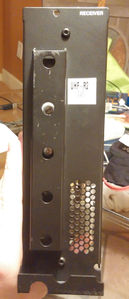
UHF RX R0 Front
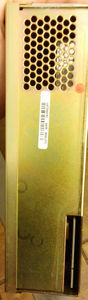
UHF RX Back
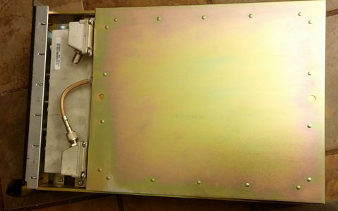
UHF RX Case
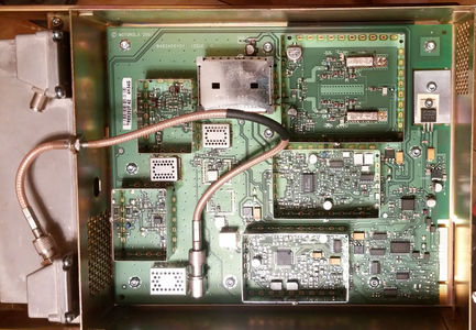
UHF RX Internal


This receiver was designed after the R1-R4 receivers and replaces the R1 unit entirely. However if an R1 is needed for compatibility the R0 will work with a simple change of resistor ROM.
The receiver is a high side injection with the 1st Lo operating +73.35 MHz higher than the receiver frequency.
The SCM knows what type of module is inserted by reading voltage divider resistors on the u2600 A/D Converter. Some of these are on ports used for other things, Change Frequency and Lock and then A8 input is used for ID. Note the resistors have the same labels on the UHF boards but on other bands the same parts have different labels. The R2606 and R2607 form a voltage divider feeding the A8 input with the computed voltage in volts.
| Range | R2449 Chg Freq | R2450 Lock | SPACE | R2606 | R2607 | A8 Volts |
|---|---|---|---|---|---|---|
| UHF R0 | 0 | 3300 | 5600 | 3300 | 1.9 | |
| UHF R1 | 0 | 0 | 1200 | 1200 | 2.5 | |
| UHF R2 | 0 | 3300 | 1200 | 1200 | 2.5 | |
| UHF R3 | 3300 | 0 | 1200 | 1200 | 2.5 | |
| UHF R4 | 3300 | 3300 | 1200 | 1200 | 2.5 | |
| VHF | R2413 | R2415 | R2812 | R2814 | ||
| VHF R1 | 0 | 0 | 2700 | 1200 | 1.5 | |
| VHF R2 | 0 | 3300 | 2700 | 1200 | 1.5 | |
| 800/900 | R2422 | R2414 | R2816 | R2815 | ||
| 900 | 0 | 0 | 1200 | 4700 | 4.0 | |
| 800 | 0 | 0 | 1200 | 2700 | 3.5 |
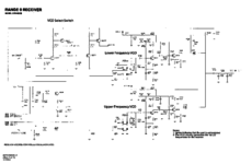
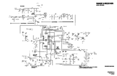
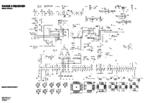
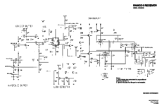
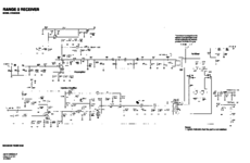
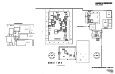
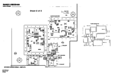
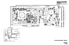
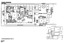
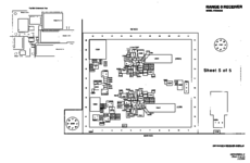
Schematics
The service manual excerpt is in PDF and below. Note the service manual says there are 12 sheets of diagrams, but only has 11. It looks to be correct.
UHF Range 0 CRX4022 Service Manual Excerpt
In PNG format.
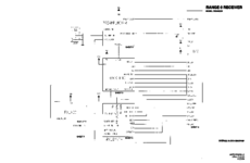
Schematic Sheet 1
Schematic Sheet 2
Schematic Sheet 3
Schematic Sheet 4
Schematic Sheet 5
Schematic Sheet 6
Schematic Sheet 7
Schematic Sheet 8
Schematic Sheet 9
Schematic Sheet 10
Schematic Sheet 11


VCO's
There are two VCO's each running 73.35 MHz higher than the operating frequency. The low covers 380-406.5 Receive, 453.35-479.85 operating, and the high covers 406.5125-433 receive, 479.8625-506.35 operating.
Each VCO consists of ceramic coaxial resonator shorted at one end as the inductive component and a laser trimmed tuning capacitor. The schematic matches the board, as Low and High are not reversed like in the R1-R4 receivers. Test point p2201 can be used to connect steering and vco select voltages to the board for testing.
As the VCO runs at 73.35 MHz higher than the intended receive frequency the VCO will expect to lock over the following ranges. The ideal spot for the VCO to operate is between 2 and 10 Volts highlighted in pink below. This steering voltage width differs from the other UHF receiver modules, due to each VCO needing to cover almost two times the range.
| Volts | Lower VCO | Upper VCO |
|---|---|---|
| 0 | 430 | 461 |
| 1 | 437 | 468 |
| 2 | 443 | 473 |
| 3 | 448 | 478 |
| 4 | 452 | 482 |
| 5 | 457 | 486 |
| 6 | 461 | 489 |
| 7 | 465 | 494 |
| 8 | 469 | 498 |
| 9 | 473 | 502 |
| 9.2 | 474 | 502.3 |
| 10 | 477 | 506 |
| 11 | 481 | 509 |
| 12 | 485 | 513 |
The advantage to the R0 VCO is it's not a sealed unit, and Motorola provides the complete schematic diagram. Note on the picture below, the higher VCO will have the shorter resonator (U2250)
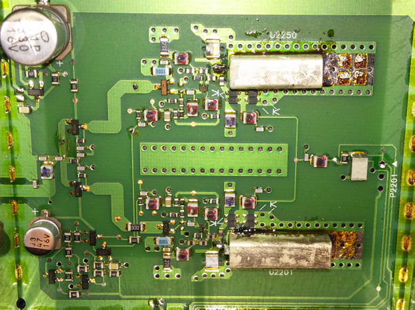
UHF R0 VCO after mod to R2

Conversions
This is a mostly complete final Draft It should be usable for converting R0 units to R2, and provide a general overview of the process. I've only converted one R0 to R2, but found it to be easier than the R1 to R2 conversion.
As always if you find anything wrong, please edit it or contact me directly. If you use these instructions please drop me a note bryan@bryanfields.net.
Converting the boards to different ranges. Only R0 to R2 has been preformed, but the others should work almost the same.
The basic premise of converting the receiver to another range consists of these four major parts:
- Convert the VCO for the proper frequency coverage
- Modify the Image filter
- Change the module ID
- Modify preselector
R0 to R1
Change the module ID. The unit should work fine as an R1.
R0 to R2
It's important to have a known good working unit on R0 before starting work. If it is not working at it's intended frequency, fix it first.
It would be good to become very familiar with the schematic and service manual before attempting this.
Tools and test equipment you should have (not an exhaustive list)
- Hot air station
- Under board pre-heater
- High quality soldering iron (metcal)
- Dual voltage variable DC supply
- Spectrum analyzer and probes
- Service monitor
- Experience working with SMD and reflow techniques
Converting VCO
The VCO is consisits of the coaxial resonators and LASER cut tuning caps. Each is shorted at one end and open at the other forming a high Q inductor.
First we'll need to remove both coaxial resonators, and move the upper one to the lower position. This is best done by preheating the board using an under-board preheater at 460f.

Once this is done, mask off the area using hole cut in some foil. This is a heat shield for the other parts of the board. Some times you need to use kapton tape to secure the foil in place.
Once you have this preheated for a few minutes, use the hot air wand with no tip 15 L/m and 650f on the shield. Move it in a circular pattern while waiting on it to reflow.
I find it's easier to remove the lower resonator first, and set it aside. Once this is done, remove the upper resonator and while the board is still warm, apply some flux and reflow it in the lower (U2201) position.
While the VCO cools down, attach some teast leads to the following points
- Ground
- +10v VCO power
- VCO select
- Variable PS (0-12v) to the steering line.

Low VCO
Hook up to the VCO as shown, we'll do the Low VCO first since it's got a resonator in it.
- 10v to power the VCO
- ground the VCO select via 1k resistor to select lower VCO
- 0-12 V on the steering line.
- output loops of wire on the VCO output. These are to be looped around a probe and into a spectrum analyzer to view the output.
A few points about VCO tuning:
- The VCO will be 73.35 MHz higher than the intended receiver frequency
- the sweet spot for the VCO steering voltage is 2-10 v
- each VCO is designed to cover half the range of the Quantar.
- The Exciter will change VCO's when it hits the range's center frequency +25khz (UHF R2 is 454.250 MHz) . You can verify this by looking at the steering voltage in the exciter as you change frequencies. A test config file (Codeplug) makes this easy.
- from hot to cold Fr changes about 1 MHz. Hotter makes Fr go down, cool makes it go up.
- grinding half the tuning cap off makes Fr go up about 20 MHz. It's very sensitive.
- removing capacitance makes Fr go up.
- removing inductance makes Fr go up.
- you may elect to move the center frequency lower on the lower VCO and higher on the high VCO if you desire a greater tuning range. I will not be showing this.
- Get it close, I'm a perfectionist, but really 2-4 MHz from ideal will not matter.
- the R0 VCO is clean from 0-12v of steering voltage.
Put 6.0v on the steering line and note the frequency on the spectrum analyzer. You can sweep it from low to high and check the coverage is correct per the table above.
We're going to align it for a center frequency of 519 MHz. The reason for this is the lower VCO covers 511-527, making the center 519. The over all shield does not seam to effect the tuning range.
There should be about half or more of the tuning cap left for this to work. If not, you'll need to replace the tuning cap with a factory new unit or grind some of the resonator down like in upper VCO tuning. .020" is a good starting point if you want to grind the resonator.
With the voltage on the steering line you should see a Fr of about 495 MHz on the spectrum analyzer. Use a diamond tip grinding tool and remove some of the tuning cap. A little makes a big difference here, half of the top is about 20MHz. Shoot for 519 MHz at 6v of steering voltage.
It's normal for the VCO to jump a couple hundred KHZ or so depending on the stability of your power supply. There is no PLL running to lock it.
Do a sweep (2-10v) and ensure it covers the intended range for the Low VCO (511-527 MHz). You want the coverage to be in the sweet spot of 2v to 10v, if it's not re-adjust it or grind some off the resonator. Generally this is not that critical.
High VCO
The high VCO is a big more complicated, as the old Low VCO resonator will need to ground with a diamond grinder. It's .850" long and needs to be .670" long. Grinding needs to be done from the non-shorted side. This will remove the center lead, but it's easy to solder a lead on it once it's installed. Go slow with the grinding and don't inhale the dust, it's toxic!
Once the grinding is done, install the resonator and fashion a center lead out of some silver plated wire and solder it in place.
Check the Fr on the spectrum analyzer, you want 535 MHz at 6V, it's best to be a bit low (long) with the resonator and then touch up the tuning capacitor with a diamond tip grinder to bring it up the frequency.

Do a sweep (2-10v) and ensure it covers the intended range for the High VCO (527-543 MHz). You want the coverage to be in the sweet spot of 2v to 10v, if it's not re-adjust it or grind some off the resonator. Generally this is not that critical.
Clean it with some solvent and let it dry.
Below is real data from a R1 to R2 conversion. The before data was taken with the shield off making the frequency about 2 mhz lower. The pink represents the sweet spot of the VCO tuning voltages. Note this covers both VCO ranges acceptably.
Image filter & Mixer
The image filter is a low pass filter which prevents the local oscillator from radiating out the receiver antenna port. This may be debatable as to the necessity of this modification as the cutoff of the R0 image filter is still above the maximum operating frequency of 470 MHz.
| Frequency | Befor mod | After Mod |
|---|---|---|
| 483.000 | -123.2 dBm | -123.5 dBm |
| 454.000 | -122.7 dBm | -123.1 dBm |
| 454.250 | -122.7 dBm | -123.1 dBm |
| 470.000 | -121.7 dBm | -122.4 dBm |
There is no difference in sensitivity, but all units which I convert I modify this for completeness.
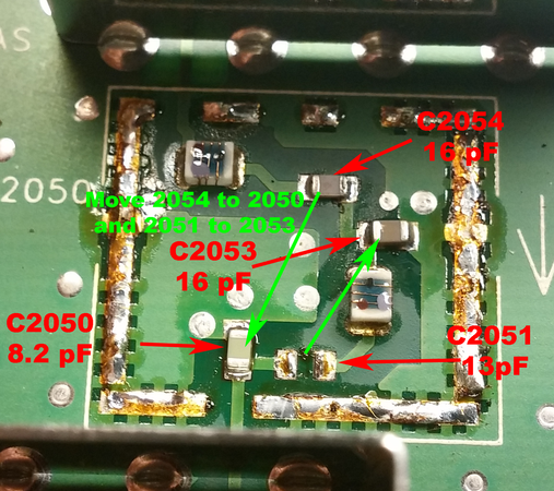
Below are the parts differences. All parts are NPO 0805 size ceramic parts. I remove all the "discard" parts first and then move the couple parts since the board is already hot.
| Part number | R0 | R2 | Notes |
|---|---|---|---|
| L2030 | 10nH | 8.2nH | discard |
| C2050 | 9.1pf | 8.2pf | discard |
| C2051 | 16pf | 13pf | move to C2053 |
| C2053 | 18pf | 16pf | discard |
| C2054 | 8.2pf | 6.8pf | Move to C2050 |
| C2057 | 18pf | 16pf | discard |
| C2059 | 18pf | 13pf | discard |
| C2076 | 7.5pf | 5.6pf | discard |
| C2083 | 47pf | 22pf | discard |
| C2079 | 9.1pf | 5.6pf | move to C2301 |
| C2070 | 5.6pf | 3.3pf | move to C2076 |
| C2301 | 10pf | 9.1pf | discard |
| R2307 | 180 ohm | 82 ohm | discard |
| R2606 | 5600 ohm | 1200 ohm | discard |
| R2607 | 3300 ohm | 1200 ohm | discard |
Some parts (C2050-C2054) are under a soldered on shield cage between the preamplifer and the 1st mixer.

Shield on
Shield off R0-R2 parts


Using a board pre-heater and hot air wand remove the shield. It does not go through the board, but be careful you do not over heat it as the inductors will melt. It's much easier than the VCO shield. Once off change the parts per the table/pictures and reinstall the shield. Note the orientation of the shield, it's designed with cutouts on the input and output strip-lines.
- Change the parts under the 1st mixer shield per the table and picture below
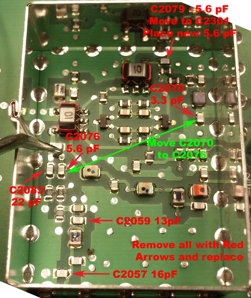
UHF 1st mixer parts moved

- Change the inductor L2030 to a 8.2 nH part under the Pre-amp shield per the table and picture below.
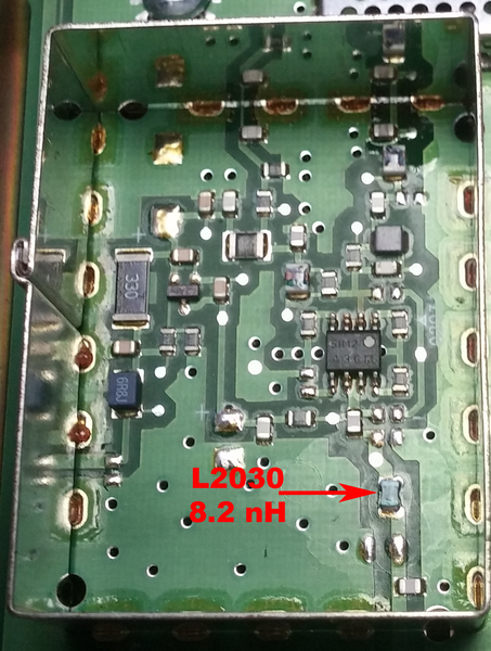
Pre-amp R0 to R2

Change the Module ID
Follow the table above and change R2607 and R2606 to 1200 Ohm parts. These a located by the synthesizer, but not inside it.
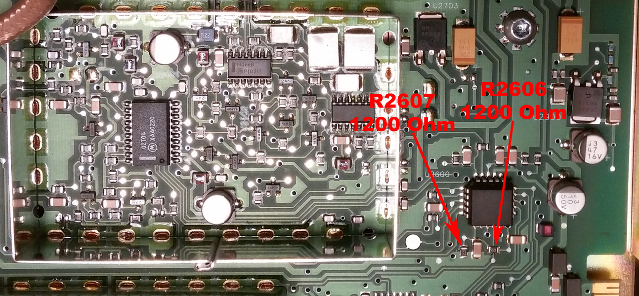
R0 to R2 ID voltage divider.

Preselector
The preselector modifications are covered elsewhere.
Final testing
Once the preceding modifications have been done it's time to test the receiver module without the preselctor.
With the power off install the RX board back in the metal case and slot it into the Quantar chassis.
Power the station on and program a test code plug with the following frequencies.
| Lock? | Steering voltage | Sensitivity | |
|---|---|---|---|
| 425.000 | |||
| 430.000 | |||
| 433.000 | |||
| 435.000 | |||
| 438.000 | |||
| 454.000 | |||
| 454.250 | |||
| 470.000 | |||
| 473.000 | |||
| 475.000 | |||
| 478.000 | |||
| 480.000 | |||
| 485.000 | |||
| 490.000 |
Use the control and metering screen to check the oscillator voltage at each frequency. Ideally you should be between 2 and 10 volts for 438.00-454.00 and 454.25-470. The other frequencies are there just to find the range of the VCO's as installed. If your minimum lock voltage is under 1v you may want to re-adjust the VCO in question. If the high frequency is above 11v you may wish to adjust as well.
Check the sensitivity of the receiver at all locked frequencies. With out the preselector installed the sensitivity should be better than -121.5 dBm or .2μV for 12dB SINAD.
Once this is verified, button it up, install the modified preselector and mark the unit as a R2 modified receiver.
Congratulations!
R0 to R3/4
No data on this yet, may be doable VCO will be a problem.