UHF Preselector
Contents
Basics
The UHF preselector is a 3 pole, low insertion loss (1.2 dB) 4 MHz wide filter. In practice this is closer to 5MHz wide.
Fun fact, the same preselectors are used in the MTR and GTR base stations too.
The preselector varies based on the band of the RX as follows
| P/N | Range | Description |
|---|---|---|
| CRX4001 | UHF R0 | UHF Preselector 380-433 MHz |
| TLE5991 | UHF R1 | UHF Preselector 403-433 MHz |
| TLE5992 | UHF R2 | UHF Preselector 438-470 MHz |
| TLE5993 | UHF R3 & R4 | UHF Preselector 470-520 MHz |
Note R3 and R4 use the same preselector. The preselector hooks up to the RX input and can be removed for testing.

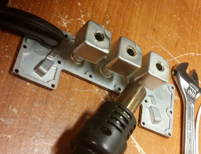
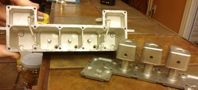
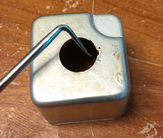
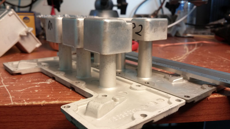
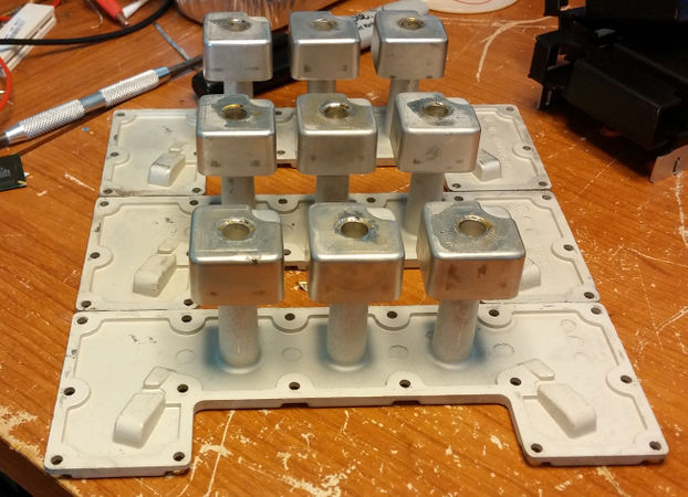
The internal design of the preselector is basically a tubular inductor and a top capacitance hat. Interesting to note the coupling takes place at the low side vs. the normal high side. The center of this hat/inductor has a hole into which the tuning screws slide in to/out of. The R0 preselector has a much longer screw, and the front panel has a protective metal part protecting the protruding parts.
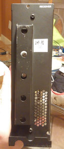
Range 0 Receiver front

The bottom of the preselector has T10 size screws on it and they need to be tightened and loosened in order of the numbers on the bottom plate. Once apart the variance in the length of the cap hat should be noticed showing the range of the preselector.
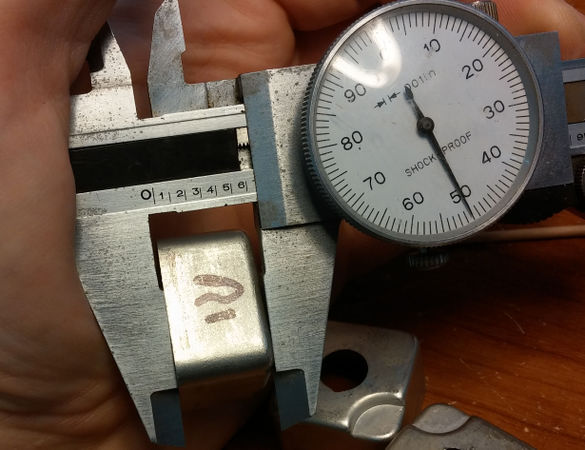
| Range | Cap Hat length (inches) |
|---|---|
| UHF R0 | |
| UHF R1 | .880 |
| UHF R2 | .650 |
| UHF R3 & R4 | .437* |
Note the R3 and R4 is based on measurement from a friend, not measured with a caliper.
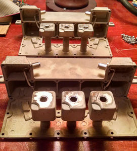
R0 in front vs a R3/4 preselector
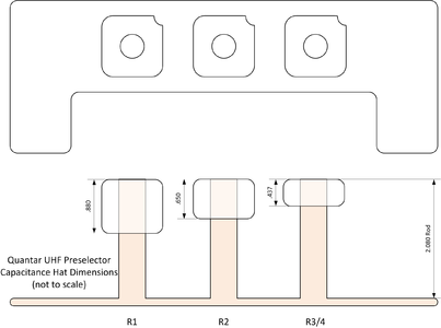
Preselector diagram


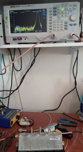
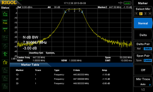
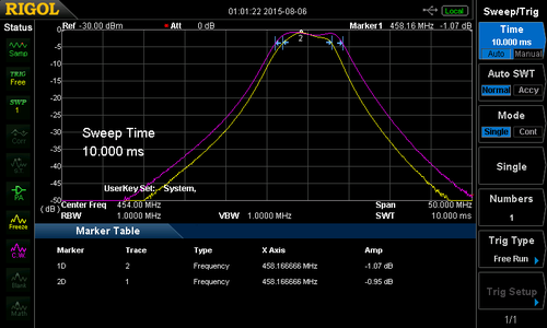
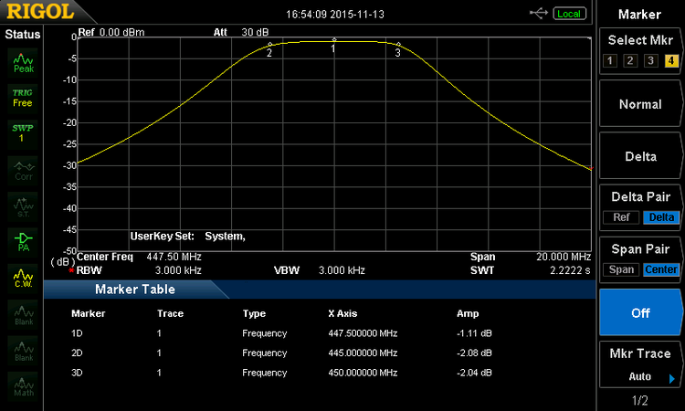
Patterns of preselectors measured with a spectrum analyzer. Note the bit of ripple in the pass band. Motorola sells a probe to be used to align the preselector via alternate peaking and diping it, but it's much easier to tune on a spectrum analyzer/tracking generator. This has the advantage allowing you to tune for the exact pass band needed. In many cases it's advantageous to tune the center off of the frequency. I find it's easy to tune the entire US 440 ham band input range as a CF of 447.5.
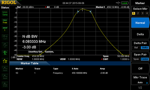
UHF R2
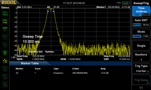
Quantar R0 at 380 MHz
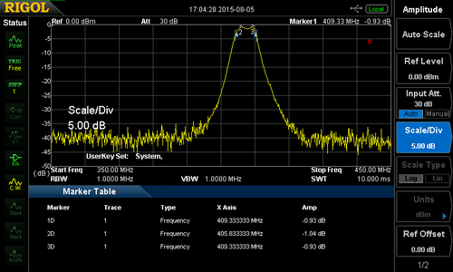
Quantar R0 at center
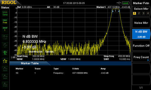
Quantar R0 at 437 MHz
Tuning a R0 preselector


Modification
Two styles of modification have been attempted on these preselectors to raise the frequency. Lowering the frequency has not been attempted (ie. R4 to R2), and all focus on moving R0/1 to R2, though the same techniques would work to move to R3/4.
Method 1: Shorting the Rod
Shortening the rods was attempted on the first modification of the R0 to R2 preselector. The cap hats were removed and the center rods were ground down .270" on each rod.
This became a problem as the rods are made of silver plated copper plated aluminum, which makes grinding a hard thing to do. It removed the tinned part of the rods where they solder to the cap hats, and the alignment "key" notched into the top of the rods. The final result was a filter which had a bit more ripple and wider than desired, but with good insertion loss.
I suspect the width was changed mostly due to moving the cap hats lower in the housing.
R0 preselector during modification
Quantar R0 converted to R2 by cutting tubes showing post modification drilling to lower capacitance
Quantar R0 converted to R2 via tub cutting sweep
R0 converted to R2 by tube cutting over lay on real R2


For the R0 filter at normal frequency the tuning slugs should be roughly as follows:
| Center | length sticking out (inches) | insertion loss |
|---|---|---|
| 380 MHz | .275 | .65 dB |
| 433 MHz | 1.140 | .60 dB |
| 437 MHz | 1.200 | .40 |
After grinding the stubs down it was necessary to use an aluminum flux and soldering iron to get the solder to adhere to the metal of the studs. This flux destroyed my Metcal tip and it had to be replaced, at a cost of $30. After this it was easy to use a heat gun and reflow the solder on the caps. The issue here is to make sure they line up as the notches are removed from the stubs during grinding.
Over all this method works, but it's much easier to cut the hats down in length.
Method 2: shortening the cap length
This is the preferred method to raise the frequency as it's more in line with the construction Motorola uses.
The procedure is as follows:
- Open the preselector and set aside screws and top case.
- Secure the bottom to a work surface and pre-heat the first cap

- Using a hot air gun heat the first cap up and remove it.
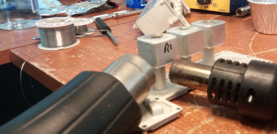
- Do the same for the rest of the caps
- Once cooled down it's time to grind the caps to .650"
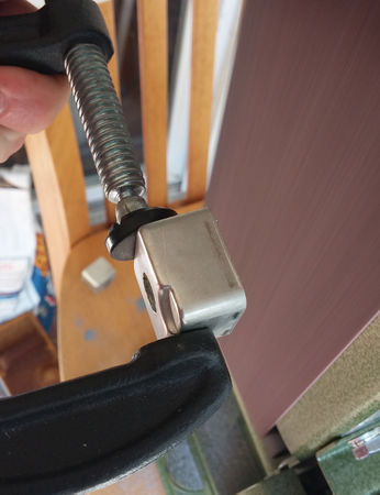
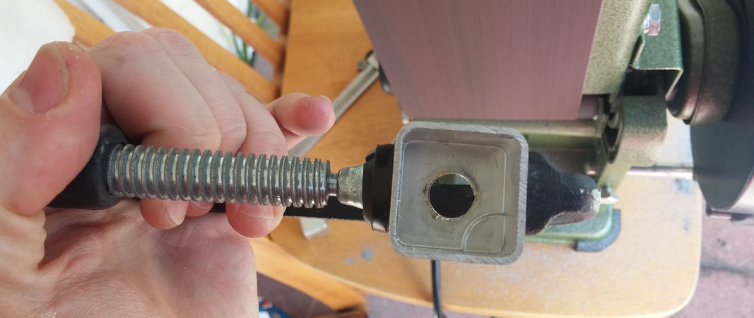
- Once all caps are the proper length, clean them in water/detergent bath. Ensure no grindings are left or able to flake off.
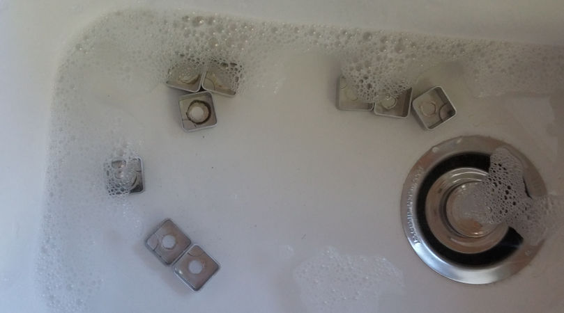
- Set the caps on the stubs, noting the alignment notch.
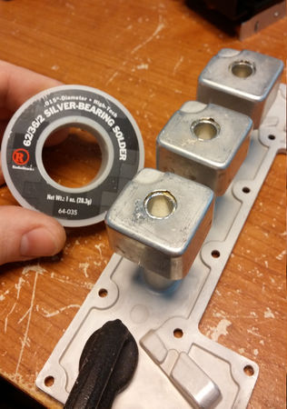
- Apply a dab of flux to the joint
- Reflow the solder with the heat gun, and add silver bearing solder to ensure a nice fillet joint.
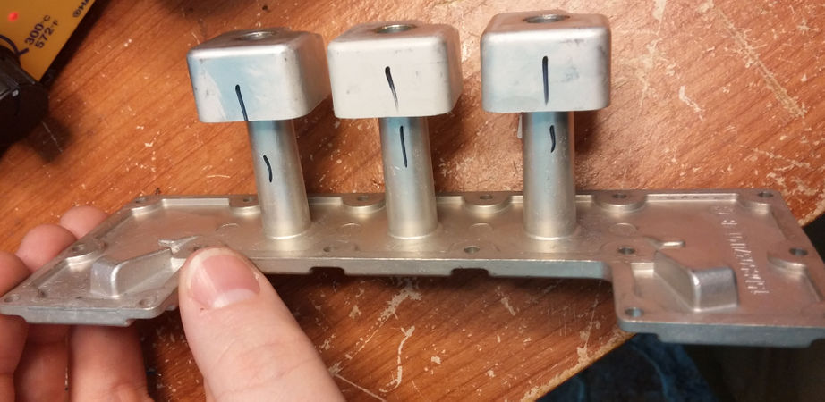
- Do this for all caps
- Allow to cool and then deflux the joints
- Reassemble the case, and tighten screws in numerical order.
- Test tuning and insertion loss at 438, 454, and 470 MHz. Loss should be a dB or less at all frequencies.
Quantar R1 to R2 UHF RX filter
Completed R1 to R2


I find it's best to score a line around the cap before grinding. You can also use a band saw to remove the majority of the metal first and then clean it up on the belt/circular sander. Clean up the rough cut on a fine sander and debur if necessary.
Remember you can only remove material, so check each corner for proper length. The length is not that critical (1/16"); try to get it as close a possible.


There is still much play in the alignment, and they may need to be adjusted once reflowed.


