800 MHz Exciter
This page covers the 800 MHz exciter in technical detail. This exciter is similar to the 900 MHz exciter and shares the VCO design. The UHF R0 exciter has this same sort of VCO design as well.
Contents
Basics
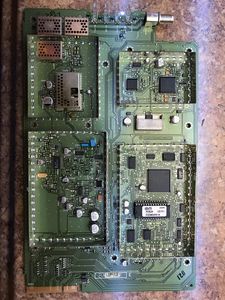
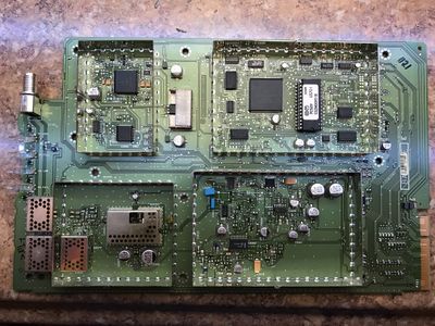
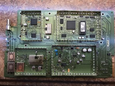
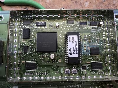
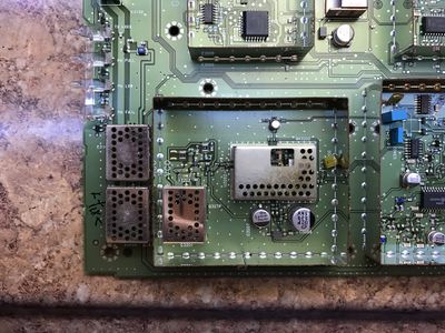
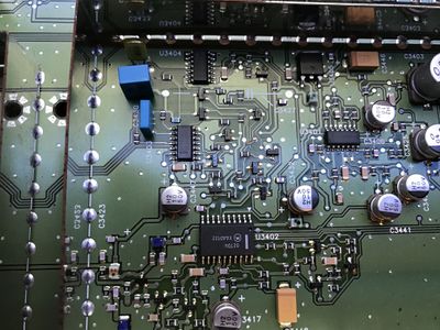
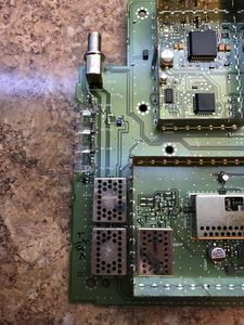
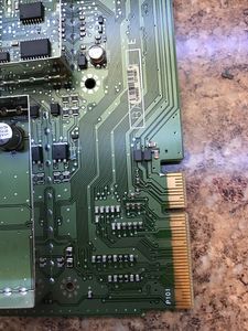
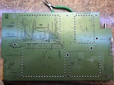
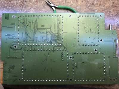
The 800 MHz exciter is pictured below. It's designed to 850-870 MHz commercial band with 12.5, 20 or 30 KHz channels using FM, VSLEP or P25 modulation formats. Like the other exciters in the Quantar series, it can switch rapidly between digital and analog formats.
Quantar 800 MHz Exciter 218
Quantar 800 MHz Exciter 219
Quantar 800 MHz Exciter 220
Quantar 800 MHz Exciter 221
Quantar 800 MHz Exciter 222
Quantar 800 MHz Exciter 223
Quantar 800 MHz Exciter 224
Quantar 800 MHz Exciter 225
Quantar 800 MHz Exciter 226
Quantar 800 MHz Exciter 227
Quantar 800 MHz Exciter 228
Quantar 800 MHz Exciter 229
Quantar 800 MHz Exciter 230
Quantar 800 MHz Exciter 231
Quantar 800 MHz Exciter 232
Quantar 800 MHz Exciter 233
Quantar 800 MHz Exciter 234
Quantar 800 MHz Exciter 235
Quantar 800 MHz Exciter 236
Quantar 800 MHz Exciter 237
Quantar 800 MHz Exciter 238
Quantar 800 MHz Exciter 239
Quantar 800 MHz Exciter 240


The 800 exciter are similar to the other exciters with the major exception of they only have one VCO (upper) to cover the 20 MHz tuning range. This tuning range is only 2%, where as the tuning range of a single UHF VCO is closer to 3.2% for 16 MHz of tuning range. As is the VCO is discrete parts we have a schematic of it available which really helps.
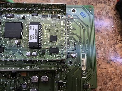
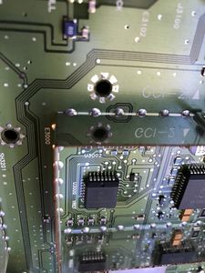
The Exciter uses the standard truth table for both the exciter ID (VHF/UHF/800/900/etc.) and the board revision. I have little ideal what the board revision is used for.
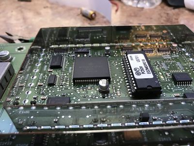
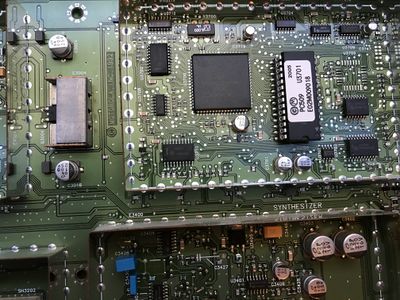
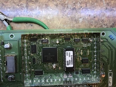
The Exciter has a CPU with firmware required to control it and reports to the station controller over a SPI bus. There is 1k of EEPROM used for storing the tuning values for the exciter and power amp in the the CPU. This allows you to tune a PA/Exciter and move it between chassis with out needing to retune. The firmware is stored on a 27C512 EPROM, and as of the current writing (Aug-2016) 020.09.018 is the most recent firmware.
The Exciter controls the PA and will shut down if the PA is not present or detects an error. The band resistors on the Exciter and PA must match, even if they are programed in the software "codeplug" to different values.
Schematics
The service manual excerpt is in PDF and below.
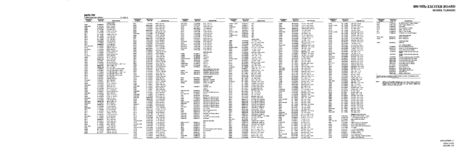
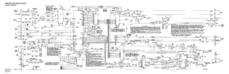
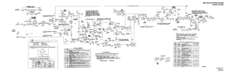
PDF Excerpt 800 MHz Exciter TLF6920G diagram
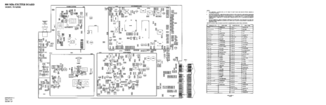
800 MHz Exciter Diagram 1
800 MHz Exciter Diagram 2
800 MHz Exciter Diagram 3
800 MHz Exciter Diagram 4


Conversions
As the 800 and 900 units are very close they can be converted to 900 MHz for amateur use. You will require a High stability oscillator or external 10/5mhz clock for 900 MHz use.
800 to 900 MHz
The basic premise of converting the 800 to 900 MHz is four major parts:
- Convert the VCO for the proper frequency coverage
- Change the module ID
- Change the module version ID
- Align the exciter/PA (not covered here)
This should cover the entire 902-928 MHz ham band after the conversion, and up to 941 MHz for the commercial band. This is wide enough to cover the 12 MHz offsets of the older 33cm ham band. The issue will be the tuning values may not work that far from the alignment points.
The exciter uses a low and high frequency to develop a modulation slope (y=mx+b) on as the same input will give different deviation as you move to a different frequency. As the tuning values are keyed off the band edges, this means at 927 MHz the transmitter will be 8 MHz outside it's lower limit. Most of the SCM's can handle this fine and it's typically a linear response, but the deviation should be checked on the intended frequency's after alignment.
If you have the EPIC 3 SCM it will not work outside the frequency limits of 935-941 MHz, and there is no work around for this (even with a real 900 MHz unit). I've investigated changing the band edges in the firmware, they are not in the code plug. If you know how to do this, please add it here.
It's important to ensure commercial band coverage as the unit will align on 935.025 and 940.0975 MHz. If the VCO can't lock this high, it cannot be aligned.
It's important to have a known good working 800 MHz unit before starting work. If it is not working at it's intended frequency, fix it first.
It would be good to become very familiar with the schematic and service manual before attempting this.
Tools and test equipment you should have (not an exhaustive list)
- Hot air station
- Under board pre-heater
- High quality soldering iron (metcal)
- Dual voltage variable DC supply
- Spectrum analyzer and probes
- Service monitor
- Experience working with SMD and reflow techniques
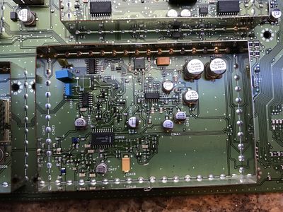
Converting VCO
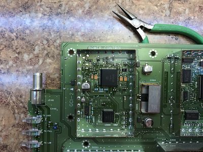
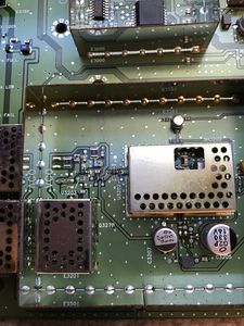
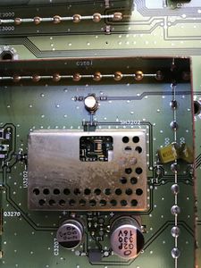
The main interest for us will be in the VCO section of the board. The VCO is covered by a shield with a laser cut tuning capacitor visible through it. There is a single VCO which covers the entire band, of 850-870 MHz, and we'll be moving this up to 915-935 MHz. Note the 900 MHz exciter has less range than the 800 exciter, this is due to the smaller tuning range needed and facilitated by C3209.
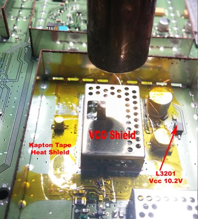
The VCO is covered by a soldered on shield. This shield must be removed before we can retune the VCO.
- First mask of the area with some kapton tape/foil of other heat shield. The other components will melt if not for this. A board pre-heater and 610 F at 15 l/m of air flow from a hot air wand will have the shield off in in about 60 seconds.
800 VCO prepped for desoldering]]

After about 60-90 seconds the shield should lift right off. Be careful and pull the shield straight up. The other parts under the shield will have been reflowed, and the slightest nudge will move them off the board. Once it's flowed, and while keeping the heat moving on the VCO case, pull the case straight up with some needle nose pliers. The case should come clean off, though you may need to rock it back and forth a bit.
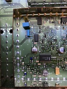
If you do move some of the parts by accident, look at the picture below and try to get them back in the same spot. There really is not much under the VCO shield to mess up, but it's critical to get it right if you do have to repair it.
At this point you may wish to hook up the VCO for testing so you can sweep the response at 800 MHz or go right into changing the components needed to move it to 900 MHz. If this is your first time, it may be a good idea to understand the response at 800 MHz.
- To hook up the VCO for testing/tuning without turning the synth chips, temporally remove L3201 and set it aside. Hook up a lead to the pad a shown with 10.2v to power the VCO on it's own.
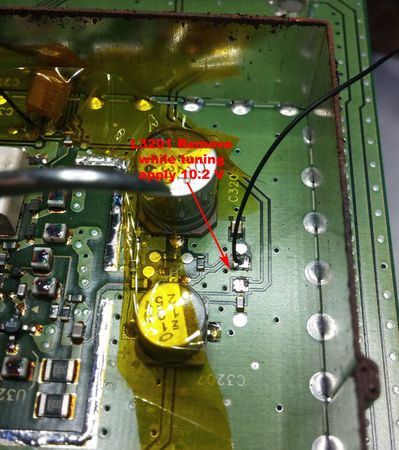
800 MHz Exciter VCO power point

- The next step is to remove the ceramic resonator from the VCO and C3212. While the board is still warm replace C3212 with a 3.3 or 3 pf 0603 NPO unit.
- Tack on a wire to the junction of C3200 and R3200 for the steering voltage to be applied. This will be where 0-9v is injected to tune the VCO.
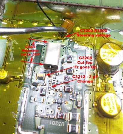
800 exciter VCO conversion to 900

Now we will modify the VCO resonator by using a diamond grinding wheel to shave the shorted end down. It's possible to do the front end but it will destroy the center conductor lead, and you will need to replace it with a small section of wire.
- Grind the resonator down to 0.320" long not including the lead.
- Now use a small piece of copper foil and solder it on the end to the outer conductor of the resonator over the end that was ground down. Solder the inner conductor to the copper foil as well. This should make a nice flat short on the end of the resonator.
- Be sure it's smooth on the bottom as you will need to solder it back down to the VCO. If you remove too much of the resonator the frequency will be too high, but you can always increase the value of C3212 if need be.
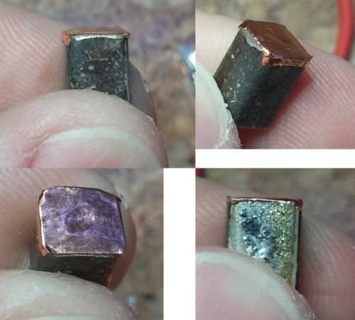
800 MHz to 900 MHz exciter resonator

The VCO shield will make the VCO frequency go up by about 2 MHz when in place as well. Keep this in mind for tuning the VCO; it's best to be 5-6 MHz low with the shield off and then correct it up with a grinder on the tuning capacitor.
Here are my notes on the tuning range of the VCO at various modification points. Note this is with the shield off. As you can see in the highlighted row, with the shield on it will cover up to 941 MHz at the upper end. This is ideal for ham band coverage.
This table shows my notes on resonate frequency of the VCO vs. part changes and trimming the resonator.
| .9V | 5v | 9v | Delta | |
|---|---|---|---|---|
| Case off pre-mod | 839 | 860 | 878 | 39 MHz |
| Only C3212 3pf | 843 | 865 | 884 | 41 MHz |
| C3121 + Trim .335 | 884 | 909 | 929 | 45 MHz |
| C3212 + Trim .320 | 895 | 920 | 939 | 44 MHz |
This provides the rough tuning to the VCO, ideally you want it 5 MHz lower than needed. If it must go up to 942 MHz at 9v, rough it in at 938 MHz. Add the shield on and check the tuning, and you can slightly grind at the tuning cap using a small diamond bit in the dremmel. Removing material will make the frequency go up, and most caps have at least half of the material remaining on them from the laser cutting at the factory.
Hook up to the VCO as shown
- 8.5 V power to VCO.
- 0-9.2 V on the steering line.
- output loops of wire on the VCO output. These are to be looped around a probe and into a spectrum analyzer to view the output.
A few points about VCO tuning:
- the sweet spot for the VCO steering voltage is 2.5-7.5 v
- with the shield on they move up about 2-3 MHz
- from hot to cold Fr changes about 1.5 to 2 MHz. Hotter makes Fr go down, cool makes it go up.
- removing capacitance makes Fr go up.
- removing inductance makes Fr go up.
- tune a bit below the frequency (5 MHz) and adjust the tuning cap after putting the shield in place
- Get it close, I'm a perfectionist, but really 1-2 MHz from ideal will not matter.
- at higher steering voltages (>9v) the VCO may get dirty. This is normal; do not exceed >15V under any circumstances.
Put 5.0v on the steering line and note the frequency on the spectrum analyzer. You can sweep it from low to high and check the coverage is correct per the table above (it will be about 2MHz higher with the case off).
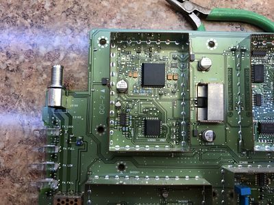
Changing the ID bits
The ID bits on the exciter tell the SCM what kind of exciter it is based on the truth table on the main page.

The differences are noted below
| Value | Band | Binary | Notes in the RSS |
|---|---|---|---|
| 4 | 800 | 000100 | |
| 11 | 900 | 001011 |

The highlighted resistors need to be swapped to change the 800 to 900 ID bits.
| Bit | Low Resistor | High Resistor |
|---|---|---|
| XXXXXn | R3700 | R3701 |
| XXXXnX | R3702 | R3703 |
| XXXnXX | R3704 | R3705 |
| XXnXXX | R3706 | R3707 |
| XnXXXX | R3708 | R3709 |
| nXXXXX | R3710 | R3711 |
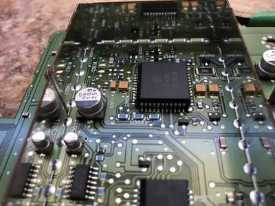
Changing the version bits
I'm not sure what the version bits mean, but the 800 Exciter and 900 Exciter have different versions. I've changed it for correctness, but I'm not sure it's necessary.


470 Ohm resistors are placed in the following places to determine if the bit is high or low.
| Bit | High Resistor | Low Resistor |
|---|---|---|
| XXXXXXXn | R3802 | R3803 |
| XXXXXXnX | R3804 | R3805 |
| XXXXXnXX | R3806 | R3807 |
| XXXXnXXX | R3808 | R3809 |
| XXXnXXXX | R3810 | R3811 |
| XXnXXXXX | R3812 | R3813 |
| XnXXXXXX | R3814 | R3815 |
| nXXXXXXX | R3816 | R3817 |
The 800 MHz Exciter is 00000001 and the 900 MHz exciter needs to be 00000011. This is done by moving R3805 to R3804 to flip that 2nd bit.