UHF Preselector
Basics
The UHF preselector is a 3 pole, low insertion loss (1.2 dB) 4 MHz wide filter. In practice this is closer to 5MHz wide.
The preselector varies based on the band of the RX as follows
| P/N | Range | Description |
|---|---|---|
| CRX4001 | UHF R0 | UHF Preselector 380-433 MHz |
| TLE5991 | UHF R1 | UHF Preselector 403-433 MHz |
| TLE5992 | UHF R2 | UHF Preselector 438-470 MHz |
| TLE5993 | UHF R3 & R4 | UHF Preselector 470-520 MHz |
Note R3 and R4 use the same preselector. The preselector hooks up to a
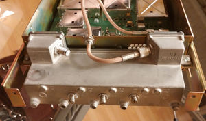
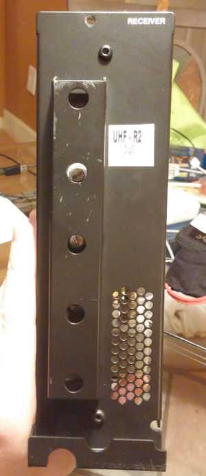
The internal design of the preselector is basically a tubular inductor and a top capacitance hat. The center of this hat/inductor has a hole into which the tuning screws slide in to/out of. The R0 preselector has a much longer screw, and the front panel has a protective metal part protecting the protruding parts.
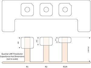
The bottom of the preselector has T10 size screws on it and they need to be tightened and loosened in order of the numbers on the bottom plate. Once apart the variance in the length of the cap hat should be noticed showing the range of the preselector.
| Range | Cap Hat length (inches) |
|---|---|
| UHF R0 | |
| UHF R1 | .880 |
| UHF R2 | .650 |
| UHF R3 & R4 |
Modification
Two styles of modification have been attempted on these preselectors to raise the frequency. Lowering the frequency has not been attempted (ie. R4 to R2), and all focus on moving R0/1 to R2, though the same techniques would work to move to R3/4.
Shorting the Rod
Shortinign the rods was attempted on the first modification of the R0 to R2 preselector. The cap hats were removed and the center rods were ground down .270" on each rod.
This became a problem as the rods are made of silver plated copper plated aluminum, which makes grinding a hard thing to do. It removed the tinned part of the rods where they solder to the cap hats, and the alignment "key" notched into the top of the rods. The final result was a filter which had a bit more ripple and wider than desired, but with good insertion loss.
I suspect the width was changed mostly due to moving the cap hats lower in the housing.


