MX800
Information on the MX800 Base Station from Spectra Engineering
Contents
- 1 General Info
- 2 Interfacing
- 3 DCS Decoder
- 4 W9CR alignment procedure and setup with Allstar
- 4.1 Initial Alignment
- 4.2 Integration of the audio delay
- 4.3 Audio interface board and Pi setup
- 5 Docs
- 6 Software
- 7 Firmware
General Info
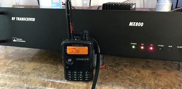
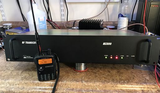
The Mx800 is a great base station for amateur use. The 220 MHz versions are now on the surplus market from Passport trunking systems that have gone bust in the mid 2000's. Motorola OEM'd these systems as a standard part of their passport config.
As they were commercial stations, they are mostly narrow band FM only. Some are switchable, but most will require a filter change and re-calibration of the transmitter to work on 5 KHz deviation used by amateur radio. The manual has a procedure on how to convert the receiver if you have SMD rework equipment.
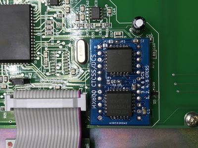
Most will require a firmware upgrade and you may wish to put a CTCSS/DCS decoder in them if you need that. My standard setup uses the CTCSS board, audio delay and Raspberry Pi based allstar controller. The advantage to the RA-35 interface is if the RPi goes offline it will fail over to in cabinet local repeat with ID on the built-in controller.
The jumpers, dip switches and nomenclature can be confusing. I've resorted to tracing out the diagrams to understand the logic inputs and have presented the settings here as my standard configuration. This may not work for everyone and there is certainly more telemetry and IO which can be done with the Mx800.
Known Issues
There has been one report of some of the electrolytic capacitors leaking, but I have not seen this
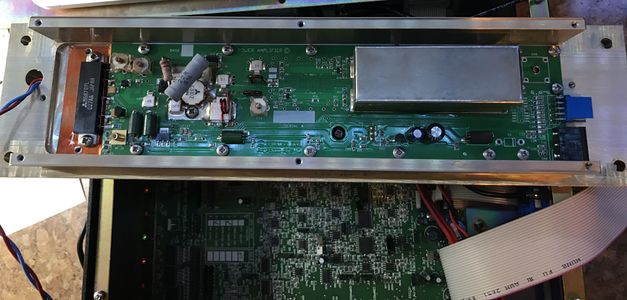
Power amp in the ham band
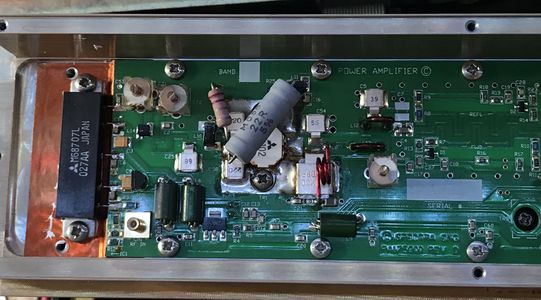
Most amps now are wide band (195-225), but I've seen a number that do not have the discrete driver transistor. They have a Mitsubishi power module as the first stage and three tuning capacitors. When peeked for maximum power (~60W) they have a 2% bandwidth. As they were tuned for 218 MHz from the factory it's worth retuning for amateur band operation. This will improve the match, which is important when followed with a duplexer.
These 218 MHz amps are not happy doing less than about 25W. Some have displayed spurious emissions when operated out of this 25-50W envelope.
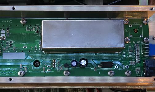
The below was a soft amp:
I've found the power out to drop off to less than 50 W (40W normal) at 225 MHz. Not sure what causes this, but I'll need to test further.
Dip Switches and Jumpers
SW 2
SW2 sets several operational cases of the station. Of the most important there is a repeater controller enable built in. This should be disabled for ham use.
| SW 2 | Function | Description | Best for Ham |
|---|---|---|---|
| 1 | PTT Delay | Enables 50mS delay of PTT for use with simplex function. | OFF |
| 2 | Simplex Enable | Enables simplex function* | OFF |
| 3 | TX Timer | Sets programmable TX time out timer on. | OFF |
| 4 | Repeater Enable | Enables repeater function - only for in box repeat. External controller should be off. This is in parallel with the Repeater Enable on Pin 8 of the DB15 Line connector. If SW2/4 is OFF the function may be controlled through this external line. JMP 14 selects the control polarity in that case. | ON |
| 5 | TX VCO on | Switches TX VCO on continuously | ON |
| 6 | Scan on | Selects the receiver to enable the scanning of programmed scan channels | OFF |
Jumpers
Jumpers set many operational aspects of the station and control audio routing. These can interplay and the nomenclature spectra engineering uses differs from what most people in North America are experienced too that it can be frustrating to figure out what really is going on.
| Jumper | Function / Description | Default | Position for
Ham use |
|---|---|---|---|
| 1 | Selects either default RUN or EMULATE mode for the micro processor. | Run | 2-3 |
| 2 | Enables the WATCHDOG auto reset function in the microprocessor. | Enabled | 1-2 |
| 3 | Enables or disables the PRE- EMPHASIS for the TX audio. | Enabled | 1-2 |
| 4 | Enables or disables the COMPRESSOR for the TX VF audio.
This isn't really a "compressor" but an amp on the VF input. |
Enabled | 1-2 |
| 5 | Enables or disables the HIGH PASS FILTER for the RX audio. | Enabled | 2-3 |
| 6 | Enables or disables the LOW PASS FILTER for the RX audio. | Enabled | 2-3 |
| 7 | Enables or disables the DE- EMPHASIS processing for the RX audio. | Enabled | 2-3 |
| 8 | Enables a direct connection to the TX modulator.
Select either Wide Band or Wide Band filtered and limited or nil. Wide Band filtered and limited means DC-4000 Hz and limited for deviation. This will have some processing on it. Wide Band is a direct connection to modulator with no limiting. |
DC-FM Limited | 1-2 |
| 9 | TX VF Loopback control. Trunking LIFUISEN function.The function polarity or nil can be selected. | Active low | 1-2 |
| 10 | Controls the direction of the RS-232 TX and RX data. | Swap | 2-3 |
| 11 | Controls the direction of the RS-232 TX and RX data. | Swap | 2-3 |
| 12 | Trunking RX Talk function.
Disables RX VF to line and TTR VF. The function polarity or nil can be selected. This is the most convoluted description. RX VF is the RX to line output. You want this output to be there regardless if there is a CTCSS/DCS tone detected by the repeater. Setting this to active low makes it output by default in conjunction with setting of Jumper 25. |
Active low | REMOVED |
| 13 | Enables or disables the HIGH PASS FILTER for the TX audio. | Enabled | 1-2 |
| 14 | Repeater enable. Trunking LIFULOCEN function.
The function polarity or nil can be selected. Note that this control is in parallel with DIP SW 2/3 |
Active low | 1-2 |
| 15 | Selects the connection for the common pin on the digital I/O connector to either Ground or + 5 volts. | ETH | 2-3 |
| 16 | Enables or disables the Low frequency HPF used for the Repeater VF routing. This removes tones from TTR audio. | HPF inline - Normal | 2-3 |
| 17 | Selects the Mute / Squelch output polarity to either normally high or low. | Active High | 2-3 |
| 18 | Trunking TX Talk function. Disables TX VF to line and TTR VF. The function polarity or nil can be selected. | Active low | 1-2 |
| 19 | Selects either internal pull up to5V or internal pull down to ETH for digital input on D25 connector | Pull up | 2-3 |
| 20 | Not Placed | ||
| 21 | Not Placed | ||
| 22 | Microphone gain. Fit this jumper to increase Mic gain 33dB | Low gain | Not fitted |
| 23 | Enable tone to speaker. Fit this jumper to enable tone | Disabled | Not fitted |
| 24 | RS232 port termination. This jumper allows an internal termination to be selected or not for bussed RS232 connections. Up to 16 units may be bussed.
All bussed bases are ‘listeners’ on the modem RS232 TX port. All bussed bases have their RS232 TX ports diode to the modem RX port. |
Normal | 1-2 |
| Normal: Non-bussed mode.
No resistor fitted. D10 out of circuit. |
1-2 | ||
| Master: Bussed mode.
4K7 resistor across D10.Configure at least one and no more than four MX800 in this mode when multiple units connected. |
2-3 | ||
| Slave: Bussed mode.
D10 fitted, no resistor. Configure balance of bussed units in this mode. |
3-4 | ||
| 25 | Mute defeat enable. Mute defeat cannot be used if RX TALK line is required.
To use mute defeat remove JMP12 and fit JMP 25. The control signal polarity can be inverted by changing the position of JMP25 |
Disabled | Not fitted |
| Active Low | 2-3 | ||
| Active High | 1-2 | ||
| 26 | CTCSS output / TX VF Loopback control | TX VF Loopback | 2-3 |
| 27 | CTCSS input / WB DC-FM input
This enables the routing of the Wide band input through a 300 Hz Low Pass filter. Ideal for an external CTCSS level |
WB DC-FM input | 2-3 |
Interfacing
Most interfacing can be done with the DB-15 port on the back, known as CN1 - Line IO. This is mapped to SKH on the PCB.
CN1
| DB-15 Pin | SKH Pin | Function |
|---|---|---|
| 1 | 15 | Alarm output #2 - Open Collector, "short to ground" when active |
| 2 | 13 | TX VF Loopback active or CTCSS output depending on jumpers
If you want TX VF input to be looped to the RX audio output when active set Jumper 9 to the appropriate position depending if input is high or low. If this jumper 9 is not placed and jumper 26 is enabled, the filtered CTCSS from the receiver will be output on this pin. This can be used for other functions externally. |
| 3 | 11 | Receiver audio from speaker amplifier. 4 ohm output. |
| 4 | 9 | Discrimator output, DC coupled, low impedance. You need a blocking capacitor on this output or you will destroy the amp. |
| 5 | 7 | Alarm output #3 - Open Collector, "short to ground" when active |
| 6 | 5 | Alarm output #1 OR M-LEAD - Open Collector, "short to ground" when active
M-LEAD is what most hams want this will give an output when configured in MX tools that COS and PL/DPL are detected. If you want to have an external controller have a PL input you want this as the PL input. |
| 7 | 3 | RX Talk - this enabled RX VF to the Line ouput and Repeater (TTR). This is needed if you want to have the RX output to line even if PL is not on it. Jumper 12 controls the polarity. |
| 8 | 1 | Internal Repeater Enable - On/Off of internal repeater function, polarity selectiable by Jumper 14 |
| 9 | 14 | Transmit Audio Input 600 ohms. Transmitter audio input to op-amps etc.Nominal line input level is -10dBm. Can handle levels between -15dBm and+6dBm. Unbalanced input with common return to analog Earth. |
| 10 | 12 | Ground |
| 11 | 10 | TX TALK. Enables or disables TX VF from line as well as TTR VF. Thepolarity is selectable via the internal jumper JMP18. If this function is notrequired then remove jumper JMP18 or place it in position 1&2. |
| 12 | 8 | PTT - The standard PTT input is active low and may be driven from standard +5V logic outputs or open collector |
| 13 | 6 | TX DC-FM Input or Wideband Input. Select the internal jumperJMP8 to configure this input as either the DC-FM input or Wide Band input.Remove jumper if not used.
DC-FM input (JMP8 in position 1-2) Audio or data may be connected to this point. In order to conform to transmitter bandwidth emissions limits, this input is hard limited to the peak deviation and Bessel filtered -3dB @ 3400Hz for minimum group delay distortion. Input impedance is >10k ohms. Input sensitivity is nominally 1Vp-p but depends upon RV2 adjustment. If this input is not used then jumper # JMP8 on the Micro Controller board should be removed to avoid any pickup of stray signals, or alternatively do not connect any wires to this pin. Avoid the use of ribbon cables longer than 30-50cm as this may result in excess coupling or crosstalk. Wide Band input: (JMP8 in position 2-3) AKA direct modulator input mode Wide band audio or data may be connected to this point. WARNING: In order to conform to transmitter bandwidth emissions limits, the signal MUST be prefiltered and level controlled, failure to do this WILL result in non-compliance of the TX emission spectrum. This input mode is not normally used except in special cases.
CTCSS Input: (JMP27 in positions 1-2) TX Subtone audio may be injected into this connection point. Input sensitivity is Fixed at 1Vp-p. AC coupled |
| 14 | 4 | COR (called RX MUTE).
The RF mute status may be monitored by reading this voltage. +5volt logic signal indicates mute status. This output is not CTCSS dependent. Output impedance approx 100ohms. The polarity is selectable via the internal jumper JMP17. |
| 15 | 2 | RX Audio 600 Ohms output
Receiver audio output from op-amp. Default nominal line level is set to -10dBm. Unbalanced output with common return to analog Earth. |
DCS Decoder
The DCS decoder works, but the CTCSS led doesn't turn on if it's received. The only indication is the M-LEAD which can be configured to be ALARM-1 or M-LEAD. This output is open collector (shorts to ground) when squelch is open and a configured CTCSS or DCS tone is received.
IC18 is the output latch for the LEDs and pin 12 will go high when M-LEAD is active. This is a convenient place to get an active high for DCS/CTCSS active.
MX800-F 220 MHz Technical Brief
W9CR alignment procedure and setup with Allstar
Presented below is the procedure and interfacing used to setup a Raspberry Pi 3 based interface with the Mx800. Using a RA-35 adapter can fail back to in-cabinet repeat if asterisk should crash or some other control problem happens. The addition of an Audio Delay board eliminates static crashes on received audio.
I use the Simple USB interface mode as I have the DCS option installed.
Initial Alignment
It's important to align the Mx800 before trying to integrate the external controller or audio delay board in the unit.
All audio levels are calibrated for -10 dBm (600 ohm) as line level.
You'll need a DB-15 connector with an DC blocking cap for testing.
Study the procedure on the pages 77-82 of the manual as this is used for the majority of the alignment.
Procedure
Setup the following channels:
- 224.400/222.800 Duplex, no tone
- Blank
- 224.400/222.800 TTR (repeat), no tone
If aligning for a specific frequency, use that in place of 224.400
Model Number
Using the access code "solderadv" in MxTools, set the model number to 25 KHz channel width.
PA Calibation
Set the sliders to lock for all channels and enable realtime updates.
With the power out slider set to maximum in the channel display of MxTools, adjust the three tuning capacitors on the PA for maximum power output.
Preform a PA calibration after this from MxTools.
Now set the power to the desired power in the channel config. Typically it's best to set this at 25-50W
Peak Deviation and Modulation Adjustment
This procedure is used to set the peak deviation and modulation balance for each channel. This can be done on a per channel basis or all channels can be set at once. The alignment is done using the Channel Screen in MxTools. To carry out this procedure the demodulated output of the transmitter output needs to be connected to a CRO or some other piece of equipment giving a visual display of the demodulated output. IF Bandwidth of the RF test set should be set at 20kHz or greater (230kHz on the HP 8920) and de-emphasise should be off. The audio filters should be set at <20Hz HPF and 15kHz LPF.
To alter all channels at once use the ‘Lock Data’ option as described in the power setup procedure. The correct peak deviation is dependent on whether the radio is narrow, medium or wide band and also whether the CTCSS option is installed. The following table specifies the peak deviation in each case.
For Wide Band with CTCSS use a peak deviation of 4.400 KHz.
JMP8 needs to be set to 1-2 for the Wide Band Input.
- Set the audio generator to +10 dBm at 1 KHz
- Key the transmitter and inject this into the WB input, Pin 12 on the DB-15, Blue Wire
- Adjust the VCO Deviation digital potentiometer using MXTOOLS until the correct deviation is obtained
- # Be sure the service monitor has enough attenuation on it for the deviation meter to work.
- Set the audio generator to +10 dBm at 400 Hz
- Adjust the Reference Deviation digital potentiometer until the top of the waveform is flat.
- Repeat these steps for best response.
When complete, select OK on the channel screen and then write the channel data to the Mx800
TX Center Frequency Alignment
The reference oscillator alignment is used to set the correct center frequency for each channel. This can be done on a per channel basis or all channels can be set at once. Oscillator alignment is done using a digital potentiometer adjustment through the Channel Screen in MxTools. To carry out this procedure the transmitter output needs to be connected to a RF test set displaying the frequency error. This procedure should be done after the deviation alignment procedure has been done. Transmitter modulation should be disabled.
To alter all channels at once use the ‘Lock Data’ option as described in the power setup procedure. Alter the Reference Oscillator Frequency potentiometer until the channel is “on frequency”. Choose ‘OK’ to accept the changes made and then from the Channel Screen choose ‘Send Data to MX800’. This then saves the changes that you have made to the radio.
TX Line Input Level and Nominal Deviation Alignment
There are three manual potentiometers associated with the TX deviation on the motherboard. These are set by injecting the correct audio levels and adjusting the potentiometers. The transmitter modulating audio is to be connected to either the WB/DC-FM input or the TX VF input as described in the procedures.
JMP- Ensure the VF compressor is enabled. JMP-8 set in position 1-2
Setup limiter gain
- Set the transmitter modulation frequency to 1kHz, -6.8 dBm injected in through the WB/ DCFM input, CN1 pin13 (Blue wire)
- Key the transmitter
- Adjust TX Limiter gain RV2 to obtain the nominal deviation.
Setup line audio input gain
For some fucking reason they call this TX VF gain in the manual.
Ensure the VF compressor JMP-4 is in position 1-2 (enabled)
General idea is -10 dBm should give 60% deviation (3khz).
- Set the transmitter modulation frequency to 1kHz at -10dBm injected in through the TX VF input. (White wire)
- Key the transmitter
- Adjust TX Limiter gain RV4 to onset of compression.
Setup repeat audio gain
For some reason they call this TTR gain. I think they just want to be different in .au
- unkey the transmitter
- Change to channel 3 (dip 1 and 2 on)
- ensure the repeater function is enabled by turning on switch 4, of DIP2
- Inject a signal into the receiver with 1 KHz tone on it and 3.00 KHz of deviation.
- Adjust TTR Deviation RV3 to obtain the same deviation as input to the receiver.
RX Line Output Level Adjustment
- Disable the repeater (switch SW4/DIP2 OFF).
- Using a 600ohm termination monitor RX line output level. This output is located on the rear of the MX800, on the Line I/O connector pin 15 of the DB15F. (yellow wire)
- Inject a signal into the receiver with 1 KHz tone on it and 3.00 KHz of deviation.
- Adjust Line Output level RV5 to obtain -10 dBm on the volt meter.
Squelch Threshold Setting
Again they call this "mute" for some reason. It's the squelch setting.
- inject a -127 dBm signal with no modulation at the receive frequency.
- Adjust the mute level potentiometer, RV6, until the squelch opens then wind it back until it just closes.
This should complete the basic alignment and your station should be set to -10 dBm line level for 60% deviation on receive and transmit. Channel 1 is setup to duplex and Channel 3 is setup to repeat.
Integration of the audio delay
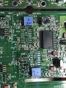
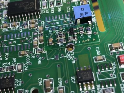
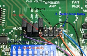
An audio delay is hooked up to the SKK connector on the station. The jumper between pin 1 and pin 2 must be removed. Leave the other two jumpers in place. This jumper cuts the audio path of the station before audio filtering feeding the line out/repeat audio/gating and after the CTCSS decoder and squelch circuit feeds. Thus with this jumper removed the CTCSS decode and squelch circuits still function, but no audio passes through the controller or out the line out.
I find wire wrap wire works well for connecting from the audio delay to this SKK connector
| SKK | ARS | Fuction | Color |
|---|---|---|---|
| 10 | Post | +5v | Red |
| 5 | 6 | Ground | Black |
| 2 | 2 | Audio In | Orange |
| 1 | 5 | Audio Out | Blue |
| 16 | 3 | COR Hi | Purple |
The below shows the hookup using this color code to the audio delay board.
Set the level control for the same input as output, this will ensure the rest of the station alignment stays the same.
The delay may be adjusted, but I find 50-100 ms is more then sufficient. The delay board from Spectra Engineering is only 40 ms and not configurable.
Double sided tape can be used to secure the delay board in the unit. Try not to route wires close to the CPU or other digital parts.
Audio interface board and Pi setup
Physical install of parts
I use the RA-35 adapter, and the level adjustment pot for the A channel. The adapter has way to much gain on both RX and TX by default with out this adjustment.
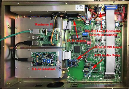
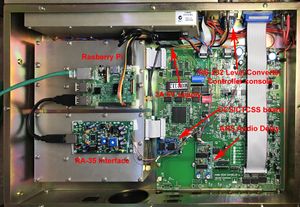
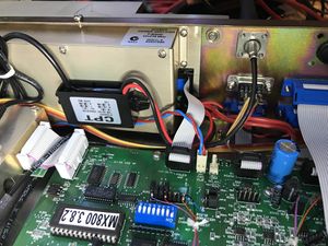
The board and Pi will sit on the exciter and receiver as shown using adhesive standoffs. Ensure you don't have any screw heads hitting the underside of the board.
The RPI is powered using a 3A 5v converter which is taped on the case of the PA. Power is taken from the connector at the side of the amplifier since it's easy to add to the screw terminal block there.
A small USB cable is used to connect the RPi and the audio interface.
A serial level converter is installed in place of CN2, Monitor IO, allowing serial console access to the RPI.
The Cat5 cable is routed out the back of the unit through the square hole under the power connector.
Wiring up the audio interface
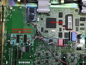
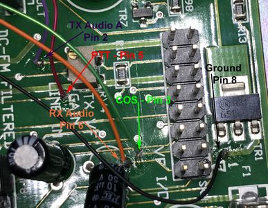
Most of the wiring is done near the SKH header for the DB-15 IO. We use the line IO which is de-emphasized, limited and -10 dBm for 3khz deviation. The IO interface is run in simple USB mode. Tone (CTCSS/DCS) is detected and generated by the Mx800, and decode status is provided to the audio interface. The receive audio is not present if the squelch is not open.
Jumper JU1 - Control Revert logic polarity should be in position B. This will pull the logic bit 1 low on the channel selector when the interface is not under asterisk control. As normal operation is on channel 1 set as duplex, this changes the base station to channel 3 (11 in binary) and channel 3 is setup as TTR (repeat) with ID.
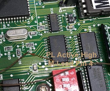
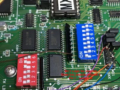
Wire up following the table below. I remove the DB-9 on the RA-35 interface to make it easier.
| RA-35 | Location | Function | Color |
|---|---|---|---|
| 3 | SKH | PTT | Red |
| 3 | SKH | COS | Green |
| 2 | SKH | TX audio | Purple |
| 6 | SKH | RX audio | Orange |
| 8 | SKH | Ground | Black |
| 4 | South of IC18
East of uP |
Tone | Brown |
| 7 | South of channel DIP
SIP-1 pin 8 |
Fail-safe | Brown |
These pictures show how everything is wired up. Since this is all internal the DB-15 is still usable for external interfacing if needed.
Configuration of Mx800 MxTools settings
Ensure the jumpers on the controller board are configured properly.
Hardware settings
- TX Reference - 13 MHz
- RX IF 90.0
- RX Low injection
- Delayed audio option checked - only added tail time into hang calculations.
- Local Remote function: enabled
- Subtone DCS option: installed
- LED settings: Standard
- Microphone not installed
- Digital IO port active state: Low
- Channel spacing: 25 KHz
Alarm settings
- Power supply monitor: out of range shutdown enabled
- Temperature settings: Fan on 35c, Over temp shut down 85c
- RF low power alarm, 25W -- Make sure this is below the actual setting for the channel if you set it to less the 50W
- Low voltage Alarm, Trip point 11v, clear point 12v
- VSWR trip point: 3:1
- Alarm tone to air: enabled
Alarm Out 1
This should be greyed out as we're using this as a M-lead for CTCSS/DCS decode status
- Active alarm out is conducting
Alarm Out 2
Trip ON:
- Low fwd power
- High refl power
- Active alarm out is conducting
Alarm Out 3
Trip ON:
- Low volts
- High volts
- Tx unlocked
- RX unlocked
- High temp
- Active alarm out is conducting
Alarm LED
Trip on:
- Low fwd power
- High refl power
- Low volts
- High volts
- Tx unlocked
- RX unlocked
- High temp
- Active alarm: LED on
Software Settings
Repeater Settings:
- Tone Tail length: 2000 ms
- Tx Tail Length: 5000 ms
- VF path: internal RX
PTT Hang time:
- PTT hang time: enable
- Tone tail length: 200 ms
- TX tail length: 1000 ms
- TX Subtone delay: 0
- RX Reverse burst: 250 ms
RF mode:
- RF Mode Port Bit : unchecked
- Repeater Delay: 0 ms
Alarm 1 routing:
- Qualified M Lead
Very important as it enables the alarm 1 output to be active low if squelch and CTCSS/DCS is decoded.
- DCS Polarity, Normal/Normal
- Ext Rx Subtone Disable: VF Only
Very important or the station will not pass audio to the Line output if set to tone squelch and only carrier squelch is active. If this doesn't pass the controller will not have audio when is carrier squelch mode.
- Channel select input: Binary
This needs to to be binary for fail-safe output to work.
- Tx Timeout Length: 0 disabled.
Morse Code Settings
This setting is configured to be used only in fail-safe repeat mode.
- Word per Min : 25
- Message Text : CALLSIGN, no other characters
- Morse Code Mode: Auto ID on Inactivity
- Auto id interval: 5 Min
Morse Code activation:
- Morse enabled
- Send only in repeat mode
Setup of asterisk
In modules.conf enable simpleusb and disable usbradio
simpleusb.conf
[general]
[usb44232]
eeprom = 1              ; EEPROM installed: 0,1
hdwtype = 0             ; Leave this set to 0 for USB sound fobs modified using

; Receiver parameters
rxboost = 0             ; 0 = 20db attenuator inserted
ctcssfrom = no		; just for testing and alignment!
;ctcssfrom = usb        ; no,usb,usbinvert
deemphasis = no         ; no de-emphasis needed
plfilter = no           ; no PL filter

; Transmitter parameters
txmixa = voice          ; Left channel output (A): voice only (no tone)
txmixb = no		; nothing on channel b
txboost = 0		; no TX boost, it's too hot!
invertptt = 0           ; Invert PTT 0 = ground to transmit, 1 = open to transmit
preemphasis = 0         ; no need for 6db/octave pre-emphasis
duplex = 1              ; Full Duplex
rpt.conf
[44232]
rxchannel = SimpleUSB/usb44232  ; SimpleUSB
Testing
Start asterisk now and see if it loads up ok. You should have the levels set at default and hear some telemetry come over the repeater. The Mx800 should be on channel 1 now.
Setting audio levels on asterisk
Ensure subaudible tones are disabled in the Mx800 and asterisk.
Setup the Transmit audio levels first:
- activate the test tone from asterisk function '*904'
- check with 'simpleusb-tone-menu' that the tx tone level is set to 500.
- adjust the tx tone level output from the RA-35 to -10 dBm. This is best done with the analog pot option on the board.
- verify this is 3.0 KHz deviation on the service monitor
- disable the test tone
Setup the Receive audio levels next:
- Send a 1 KHz tone at 3 KHz deviation into the receiver.
- verify this is -10 dBm on the line level
- adjust the audio level on the RA-35 input
- in 'simpleusb-tone-menu' adjust the level until the RX-VOICE-DISPLAY level is just under the 3 KHz mark.
- save the settings and turn off the service monitor.
The audio interface is now calibrated for a -10 dBm level for 60% deviation. The audio via asterisk should sound the same level as in cabinet repeat audio now.
You may now enable PL in the channel settings in MxTools and enable PL in asterisk if you are using it. A setting of 6 in MxTools channel for PL should be used for wide band PL, and it will translate to ~500 Hz of modulation.
Docs
Software
MXtools is the software used to manage the radios.
MXtools V3.1.8028 - Needed for >3.6.0 Firmware.
All these need a password to program the radios, and have different access based on the password used.
  'solder' -  basic password, lowest access
  'solderall' - more advanced password
  'solderadv' - more advanced, looks like you can change the model number using this and the channels from narrow/wide
  'solderusa' - not sure
  'solderalllc' - looks to be the best
Firmware
The firmware sits on a 27C512 64k byte EPROM.
Release notes MX800 Firmware History.txt
Spectra mx800 27c512 firmware image v2.9.6.bin
Spectra mx800 27c512 firmware image v3.0.5.bin
Spectra mx800 27c512 firmware image v3.1.02.bin
Spectra mx800 27c512 firmware image v3.2.5.bin
Spectra_mx800_27c512_firmware_image_v3.5.7.1.bin
Spectra_mx800_27c512_firmware_image_v3.5.14.0.bin
Spectra_mx800_27c512_firmware_image_v3.6.4.2.bin
Spectra_mx800_27c512_firmware_image_v3.6.5.00.bin
Spectra_mx800_27c512_firmware_image_v3.6.8.00.bin
Spectra_mx800_27c512_firmware_image_v3.7.1.2.bin
Spectra_mx800_27c512_firmware_image_v3.7.5.0.bin
Spectra_mx800_27c512_firmware_image_v3.8.0.0.bin
