Second Generation PA
The Quantar Second Generation UHF Power Amps cover UHF R0, R1, R2, R3 and R4. This is the second generation that Added the extra 20 MHz on the bottom of R1 (380-433) to get R0. R1 is redundant at this point.
Contents
Basics
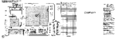
The Basic module is pictured below.

The major parts of the PA are
- Printed circuit board
- Intermediate PA
- Final PA
- Circulator
- Low Pass Filter
Each of these parts varies depending on the range of the PA.
| Band | IPA | FPA | Circulator | LPF |
|---|---|---|---|---|
| R0 | CTX5091 | CTX5093 | 5884911T33 | CTX5092 |
| R1 | CTX5091 | CTX5093 | 5884911T33 | CTX5092 |
| R2 | CTX5091 | CTX5093 | 5884911T33 | TTE6332 |
| R3 | TLE9160 | TTE6323 | 5884911T18 | TTE6334 |
| R4 | CLE6090 | TTE6342 | 5884911T18 | TTE6334 |
The R3 and R4 module part numbers are the same as what's in a generation one amplifier. R0-R2 is new parts which cover the whole frequency range (380-470 MHz) with the exception of the R2 LPF.
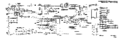
The IPA module is a 10 W output that feeds into the FPA. Note the schematic diagram has some errors on it regarding a 30-35W output from the IPA. This is an error as it's from the 25W UHF PA diagram. Unfortunately there is no diagram of the IPA or FPA modules.
The FPA module consists of two parallel PA strips with two FET's each for a total of four devices. Each strip is addressed as "A" and "B" in the radio for the current monitoring of the PA. In the CTX5093 FPA the FETs are a real MRF9045LS, giving some hope that the FPA may be repaired in the event one fails. I've used a 1200W hot air gun as a board heater and a Hakko hot air gun to spot heat the transistor to remove one. I've never tried to install one in this manner.
It's interesting that Motorola is using a part rated for 45W at 960 MHz down at 380-470, meaning they had to characterize the parts at that frequency. They have a total of 180W of power available in this design, and while they loose some in the Wilkerson combiners, it's a very robust design.
Note there is no CPU or even much digital circuitry in the PA. All metering is done via the exciter CPU mostly using an analog input and switches (U4103/4) to switch this input between different voltages on the PA.
The exciter controls the output power by an analog output (V_CONT) 0-5v from the CPU. This voltage is then used to control a couple transistors (Q4100 & Q4101) making the V_OMNI voltage that varies the first stage in the Intermediate PA.
The complete schematics are PNG format and are also available as a
PDF
Layout
Schematic Diagram 1
R0 Distribution Board
R0 Distribution/Amp board
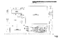
R0 Distribution Board Layout


Pictures
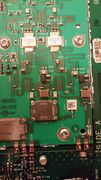
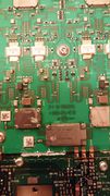
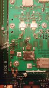
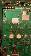
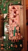
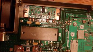
This is a UHF R0 Generation 2 PA I took pictures of.
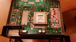
Quantar UHF Range 0 Second Generation Power Amplifier
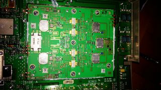
Quantar UHF Range 0 Second Generation Power Amplifier
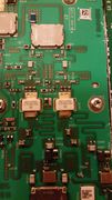
Quantar UHF Range 0 Second Generation Power Amplifier
Quantar UHF Range 0 Second Generation Power Amplifier
Quantar UHF Range 0 Second Generation Power Amplifier
Quantar UHF Range 0 Second Generation Power Amplifier
Quantar UHF Range 0 Second Generation Power Amplifier

Quantar UHF Range 0 Second Generation Power Amplifier
Quantar UHF Range 0 Second Generation Power Amplifier
Quantar UHF Range 0 Second Generation Power Amplifier


Conversions
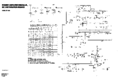
PA ID is done via a resistor "ROM". This is a voltage divider on an analog input on the exciter. It appears to be in half volt increments and the exciter split must match the PA.
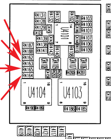
Layout of PA ID Resistors in the PA
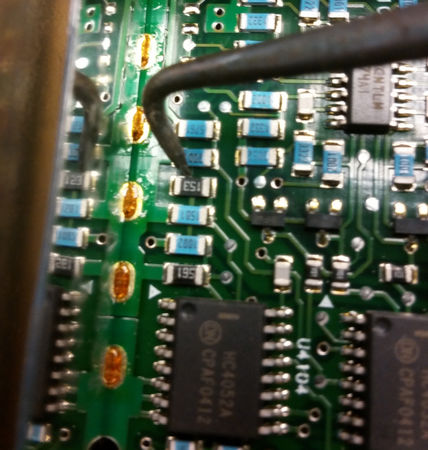
Pictures of ID Resistors


Note the arrangement of R4164 and R4165 in the layout, they do not go in order!
| PA Type | PA_ID_A | PA_ID_B | R4162 | R4163 | R4164 | R4165 |
|---|---|---|---|---|---|---|
| UHF 110W R0 | 0.0 | 1.5 | OPEN | 0 | 390 | 1k |
| UHF 110W R1 | 1.0 | 0.5 | 15k | 1.5k | 560 | 10k |
| UHF 110W R2 | 1.5 | 0.5 | 1k | 390 | 100 | 1k |
| UHF 110W R3 | 3.0 | 1.0 | 2.2k | 2.7k | 1.5k | 15k |
| UHF 100W R4 | 3.5 | 1.0 | 18k | 15k | 1.5k | 15k |
R0 to R2
Converting from a R0 to R2 is quite easy.
The major components will cover the R2 band fully. The IPA, FPA and circulator are the same with only the LPF being different.
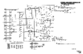
The LPF is different but there is not any problem with using it for R2. I need to test the R0 LPF at R2, as I've not swept the R0, but I suspect it's substantially similar to the R1 Gen 1 module I did sweep.
Below is a sweep of a Gen 1 LPF; R1 & R2 were swept with key data points taken as you can see below.
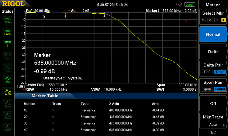
UHF R1 Power Amplifier Low Pass Filter sweep
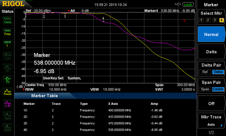
UHF R2 LPF (Purple) overlay on R1 (yellow)


The only thing necessary to convert the R0 to R2 is to change the ID resistors.
R2 to R0
Should be the same as R1 to R2
R3/4 to R2
I've never seen the R3/4 amp modules. The Gen 2 R3/4 parts are the same as the Gen 1 leading me to believe their may not be a Generation 2 version of these module. This would make sense as only the R0 was added after the fact.
Never attempted. The IPA, FPA, LPF and circulator are different. I would assume the IPA and FPA would be good. The circulator most likely needs to be changed, and harmonics checked, as the LPF cutoff is higher.
If anyone wants to try it and document it, please add it.
R3 to R4 or R4 to R3
Never attempted. The IPA, and FPA are different, but most likely will work as it's a ~5.4% frequency shift. The circulator and LPF are identical on these units so it should be only a matter of changing the ID.