800 MHz 100W PA
The Quantar 800 MHz Power Amp is designed to cover the 850-870 MHz band. It includes a built in single stage circulator and low pass filter
Basics
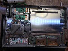
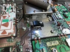
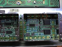
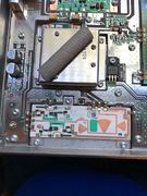
The Basic module is pictured below.
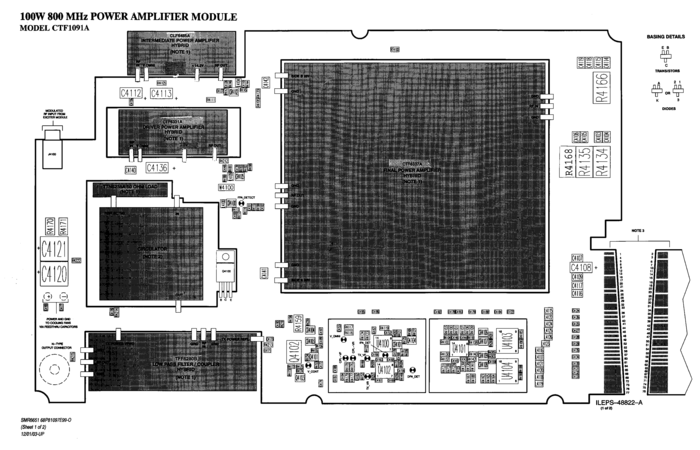
800 MHz POWER AMPLIFIER MODULE Layout

The major parts of the PA are
- Printed circuit board
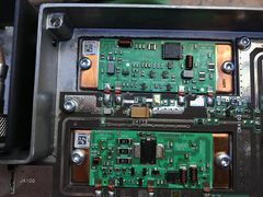
- Intermediate PA
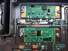
- Driver PA
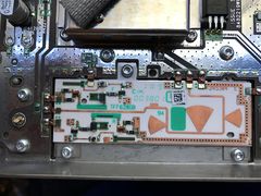
- Final PA
- Circulator
- Low Pass Filter
Each of these parts varies depending on the range of the PA. Note the Circulator is the same between 800 and 900 PA's.
| Band | IPA | DPA | FPA | Circulator | LPF |
|---|---|---|---|---|---|
| 800 | CLF6485A | CTF6331A | CTF6337A | 5884911T06 | TFF6280B |
| 900 | CLF6485A | CTF6348A | CLF6496A | 5884911T06 | TLF7150A |
The IPA module is a 1.5 W output that feeds into the DPA. The DPA takes this and ups it to 5-15W depending on the VOMNI control voltage. The passes into the FPA which can output 140-160W.
Unfortunately there is no diagram of the IPA or FPA modules.
The FPA module consists of two parallel PA strips with two FET's each for a total of four devices. Each strip is addressed as "A" and "B" in the radio for the current monitoring of the PA.
It's interesting that Motorola is using a part rated for 45W at 960 MHz. They have a total of 180W of power available in this design, and while they loose some in the Wilkerson combiners, it's a very robust design.
Note there is no CPU or even much digital circuitry in the PA. All metering is done via the exciter CPU mostly using an analog input and switches (U4103/4) to switch this input between different voltages on the PA.
The exciter controls the output power by an analog output (V_CONT) 0-5v from the CPU. This voltage is then used to control a couple transistors (Q4100 & Q4101) making the V_OMNI voltage that varies the first stage in the Intermediate PA.
The complete schematics are PNG format and are also available as a PDF
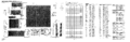
800 MHz POWER AMPLIFIER MODULE-1
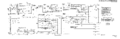
800 MHz POWER AMPLIFIER MODULE-2
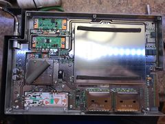
Pictures
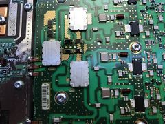
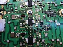
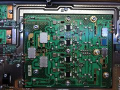
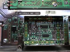
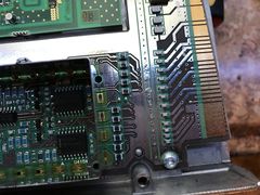
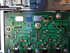
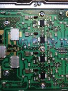
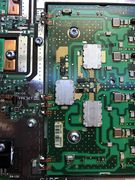
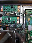
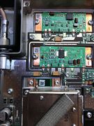
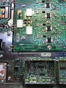
This is an 800 MHz unmodified PA I took pictures of.
Quantar 800 MHz PA 01
Quantar 800 MHz PA 02
Quantar 800 MHz PA 03
Quantar 800 MHz PA 04
Quantar 800 MHz PA 05
Quantar 800 MHz PA 06
Quantar 800 MHz PA 07
Quantar 800 MHz PA 08
Quantar 800 MHz PA 09
Quantar 800 MHz PA 10
Quantar 800 MHz PA 11
Quantar 800 MHz PA 12
Quantar 800 MHz PA 13
Quantar 800 MHz PA 14
Quantar 800 MHz PA 15
Quantar 800 MHz PA 16
Quantar 800 MHz PA 17
Quantar 800 MHz PA 18
Quantar 800 MHz PA 19


Conversions
The 800 PA is sufficiently broadband to work up at 940 MHz. In testing with a signal generator, the PA continued to make rated power out to 965 MHz and made about 70W up to 999 MHz (the top range of the generator).
800 to 900 MHz
First we need to set the physical PA ID bits.
PA ID is done via a resistor "ROM". This is a voltage divider on an analog input on the exciter. It appears to be in half volt increments and the exciter split must match the PA.
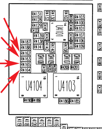
Layout of PA ID Resistors in the PA
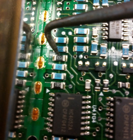
Pictures of ID Resistors


Note the arrangement of R4164 and R4165 in the layout, they do not go in order!
| PA Type | PA_ID_A | PA_ID_B | R4162 | R4163 | R4164 | R4165 |
|---|---|---|---|---|---|---|
| 900 100W | 3.0 | .5 | 20.5k | 10k | 1k | OPEN |
| 800 100W | 0.5 | 1.0 | OPEN | 0 | 1.5K | 15K |
Even though the IPA/DPA/PA/LPF are different from the 900 MHz PA they cover the band with full output. The circulator is the same unit and covers 850-960 MHz.
The LPF is concern, but in testing for insertion loss the roll off is still sufficiently high to work at 947 MHz which would be the highest frequency for the commercial band. The difference was .12 dB more insertion loss which is about 3W of additional dissipation.
Below is a sweep of a 800 and 900 LPF; 800 is in yellow and 900 is in pink and swept with key data points taken.
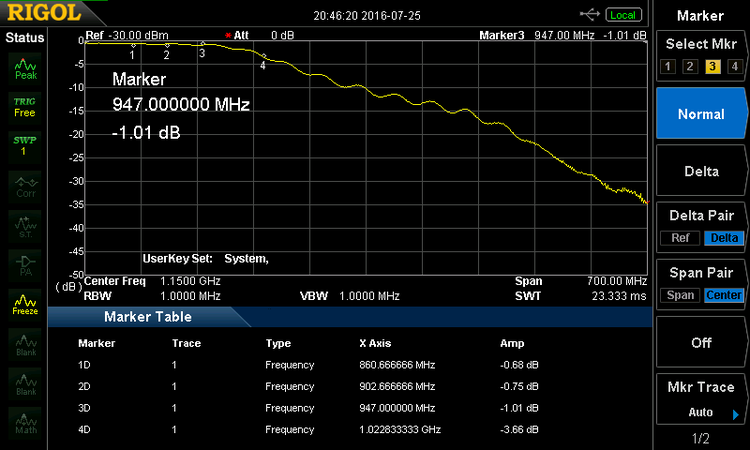
800 MHz Filter response
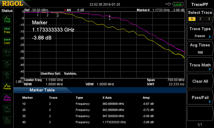
900 purple and 800 yellow LPF


The only thing necessary to convert the 800 to 900 MHz is to change the ID resistors and then re-tune.
PA Fan
A number of 800 MHz PA's have the PA fan's run continuously. I'm not sure why this is, but it's caused by a removal of an inductor L4123 on the PA. I've tested this by jumpering it back in place, and it does start the PA fans after it warms up, but it fails to shut it off again. More investigation is required, if you know please update this.
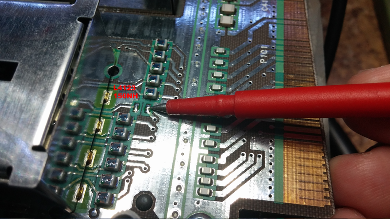
800 MHz PA Fan control inductor
