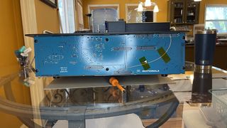
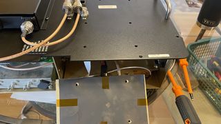
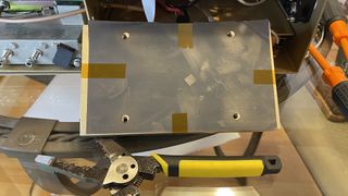
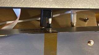
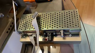
PDR 3500
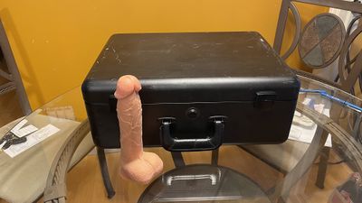
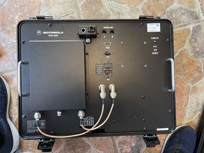
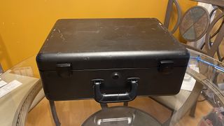
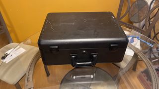
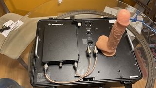
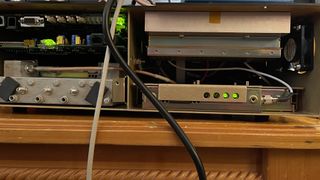
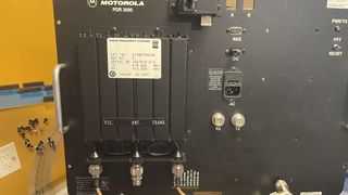
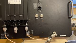
This is a page about the PDR3500 Transportable Repeater, a portable version of the Quantar. The come in an attractive case, and with flexible power options.
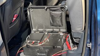
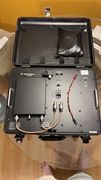
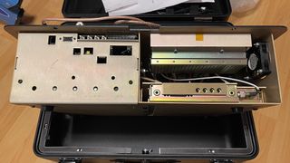
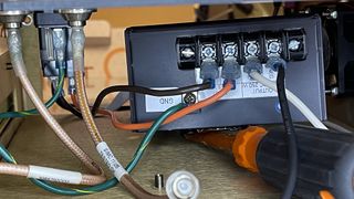
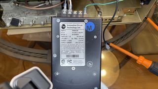
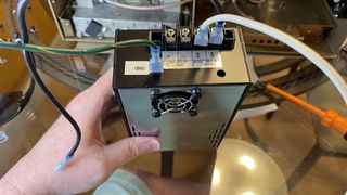
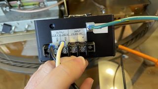
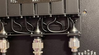
These are cool stations that take the standard Quantar modules. They are able to be powered from AC or 13v DC power, as the internal amplifier is 12v DC powered. The internal supply can work on 85-250V AC 50-60Hz, and there is a DC input for 13.8v at 10a. The unit weights about 50 lbs with the duplexer.
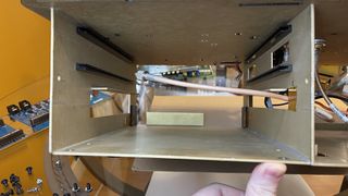
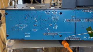
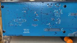
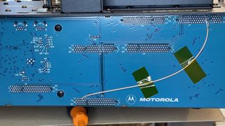
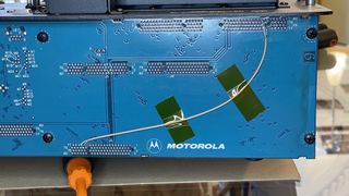
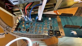
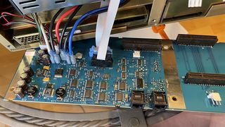
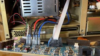
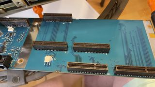
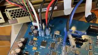
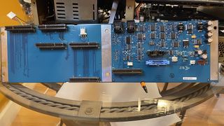
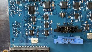
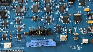
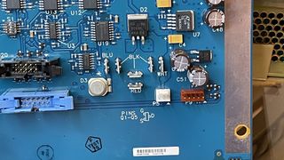
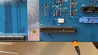
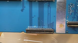
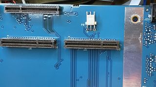
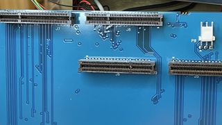
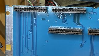
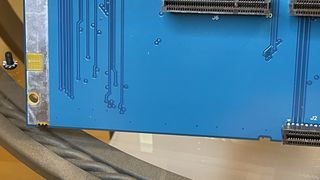
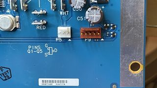
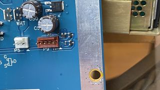
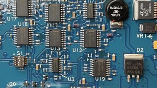
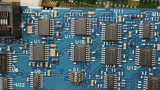
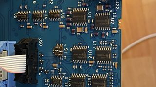
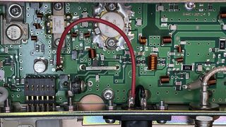
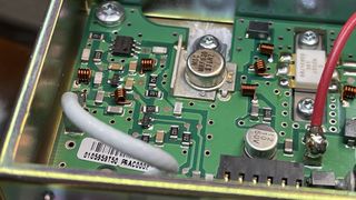
The station backplane is different here in that the PA ID is set using a 4 bit dips witch on the unit. This also adapts the SPECTRA PA module to the Quantar exciter, fooling it into thinking it's a Quantar PA.
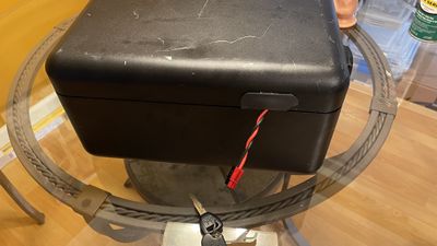
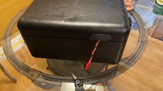
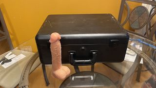
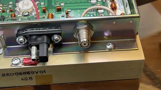
The PDR3500 can be operated with the case closed and locked (using a Chicago 2135 key) with the power and coax going out the left side of the unit through a gasket.
These were common for FBI/USSS/WHCA meaning the UHF1 was the most common (403-433), but they can be changed to UHF 2 with a module swap or via converting the units. The Spectra PA in UH1 works up to 470 MHz at reduced power and up to 465 with the full 30W. Being these were used as a backup it's common to find the 8 wire Wireline card in them. Most were later production modules so they have EPIC V modules.
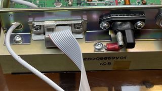
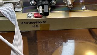
It is possible to add a v.24 card on these and route the v.24 out of the chassis.
Of note when programing it, and especially for flash upgrades, the serial port on the top is the Back Port and uses the 193.0.0.4 IP address and BP config for SLIP. I've never been able to flash these at 38400, and have always needed to use 9600 bps.
Contents
Changing Bands
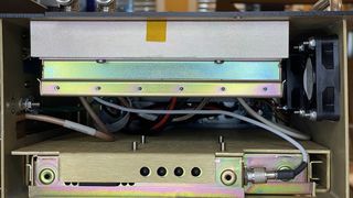
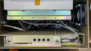
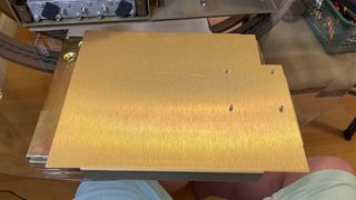
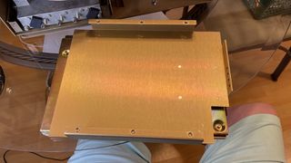
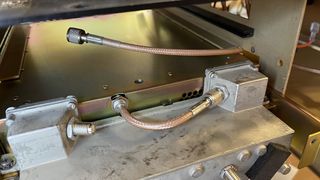
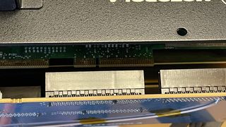
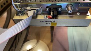
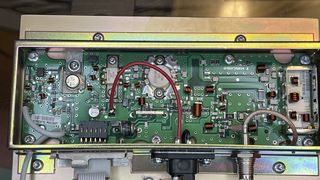
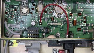
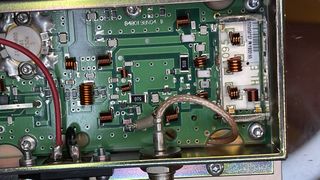
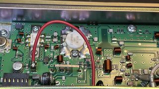
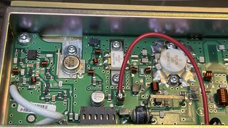
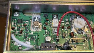
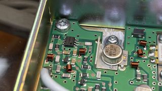
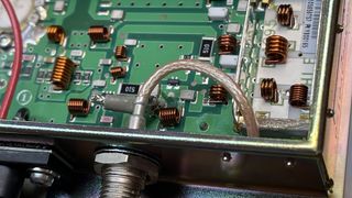
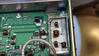
As the unit takes the standard modules, you can easily change bands by moving modules. The issue is the PA is an adapted from the SPECTRA Mobile radios, and uses the same PCB but mounted on a custom heat spreader.
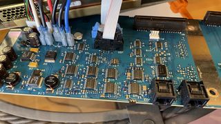
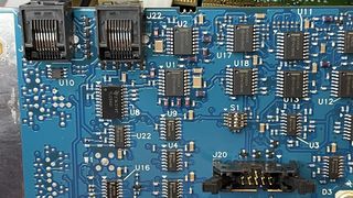
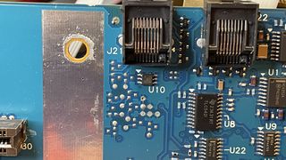
A and B RJ 45
These are the wireline interface. As the PDR manual doesn't give them anywhere they are below.
| PDR3500 - A - J21 | ||
|---|---|---|
| RJ45 | Color | Function |
| 1 | W/Orange | LINE1 + |
| 2 | Orange | LINE1 - |
| 3 | W/Green | LINE2 + |
| 4 | Blue | LINE2 - |
| 5 | W/Blue | Ground |
| 6 | Green | RDSTAT + |
| 7 | W/Brown | RDSTAT - |
| 8 | Brown | EXTPTT - |
| PDR3500 - B - J22 | ||
|---|---|---|
| RJ45 | Color | Function |
| 1 | W/Orange | LINE2 + |
| 2 | Orange | LINE2 - |
| 3 | W/Green | LINE1 + |
| 4 | Blue | LINE1 - |
| 5 | W/Blue | Ground |
| 6 | Green | 5v @ 1A |
| 7 | W/Brown | EXTPTT + |
| 8 | Brown | Ground |
Adding a Channel selector
The Quantar can support up to 16 channels, and most UHF duplexers can support a 75-100 kHz or better spread, so it makes sense that you can have 3-4 channels programmed at different options, ie. mixed, analog, P25, tones, power output, etc. This way if you come into a location and find interference on your primary channel, a quick change can be made.
The best option is a binary output 16 position switch. These will provide 0000 - 1111 input to the IO pins directly, without needed a diode array.
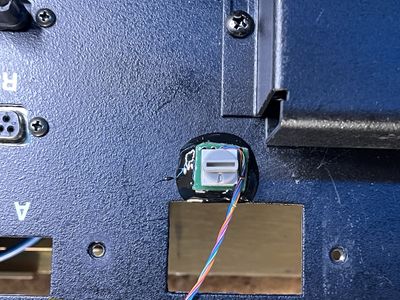
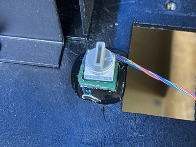
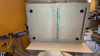
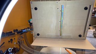
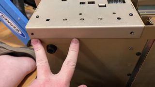
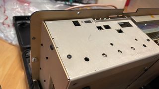
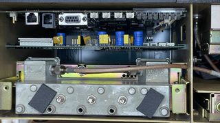
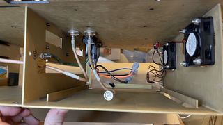
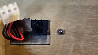
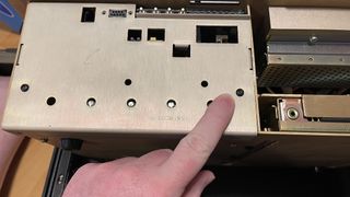
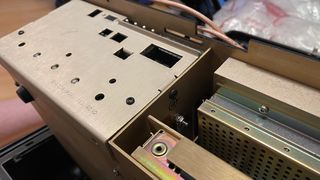
APEM makes a 0-F Hex switch PT65503, Digikey 679-1940-ND which has a nice readout and is small. I put this on some perf board and mounted it with some epoxy to the chassis. The position chosen avoids the possibility of damaging the switch with the case closed and provides a nice way to get the wires to the backplane. You can note the extra hole next to the v.24 connector, it was my first attempt with a junkbox rotatory switch. It worked great until I shut the lid and it broke the switch.
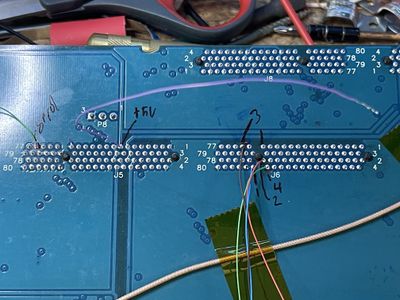
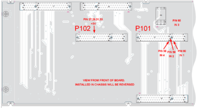
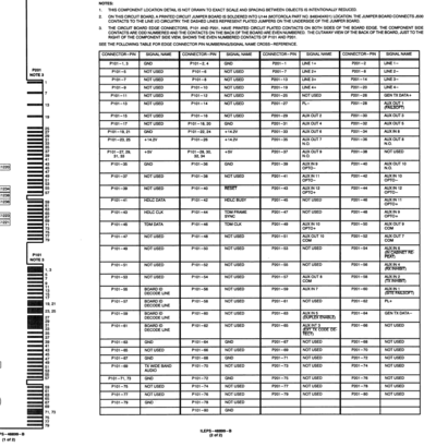
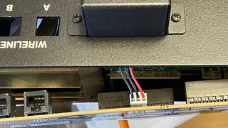
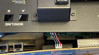
Normally this is done via the wireline board IO, and while the PDR has a wireline board, it doesn't have the IO connector. Connecting to the pins on the back plane is what's needed, and it is rather easy to do. P101 and P102 correspond to the wireline edge card connector functions.
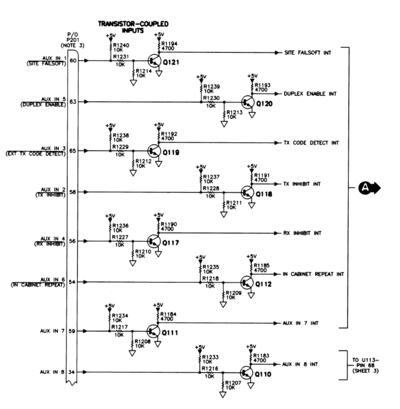
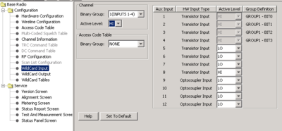
The inputs 1-4 are used in this example. They are transistor coupled and will be programed as active high. This means we must have a 1k resistor to ground on the inputs to bias them off normally.
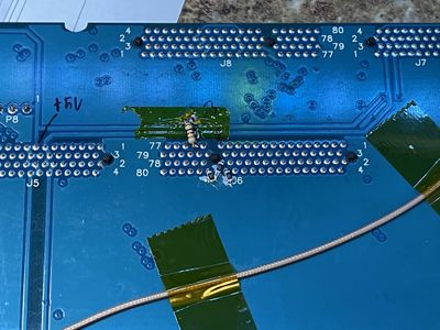
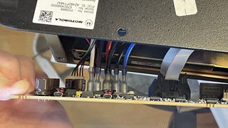
The easy way to do this is using 1206 sized or 1/8w axial leaded 1k resistors on the board it self. Using a small screwdriver scratch away some of the resist and tin the board. Install the resistors as shown. Note the small little notch to the top of the board. This is the location we will bring the wires through. If needed, use a grinder and expand this cutout.
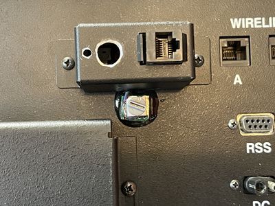
Now we need to attach the switch to a small section of PCB and attach some wirewrap or other fine wires to it. This must be epoxied to the top of the chassis, just below the v.24 connector and to the top right of the duplexer. It's suggested to lightly sand under this and clean it with acetone or other cleaner.
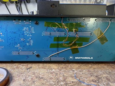
Now route the wires into the back of the chassis and connect them to 5v on the common and 1,2,3,4 to 1,2,4,8 on the switch. Once done, tape the wires in place using some kapton tape.
Finally check the v.24 bracket for clearance on the wire, and if needed grind some of it to permit the wire to fit. A protective wrap of tape or shrink tube may be needed here.
Finally you must program the wireline to use the 1-4 inputs as the channel selector. You should make a codeplug with 16 channels to test as well. Note that 0 on switch channel 16, 1-9 are the 1-9 channels and a-f is channels 10-15. If making a label for the repeater it's suggested you use 0-F to label the channels, not what RSS calls them. This will make it easier for someone in the field to select the proper channel.
Finally you want to test this, and it can be done using the RSS, or using a 9600 8n1 serial console. If using the serial console, put the repeater in RSS mode with 'dorss', then issue 'get chn cur' to see the current channel. confirm the channel selected works as expected.
Documents
PDR 3500 Transportable Repeater Basic Service Manual - This has the backplane diagram and layout in it as well.
Pictures
External
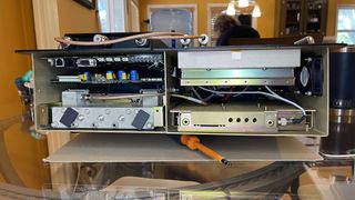
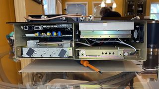
Internal
Chassis And Backplane
Power Supply Module
Duplexer
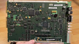
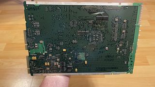
EPIC V SCM
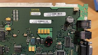
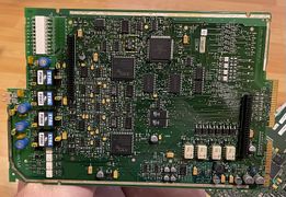
Wireline
UHF R1 PA Module
Note this is the module from an Astro Spectra/Spectra mid power unit
