Uniden MRS904
Contents
Overview
The Uniden MRS-904 is a 898-901/937-940 MHz band LTR trunking repeater designed by Uniden in the early 1980s. It was intended to be used in an eco-system of controllers and accounting systems enabling the operator to charge individual users for their airtime. Independent operators would buy them and sell service on the new 900mhz commercial band in the days before cellphones.
The basic repeater does 2.5 KHz deviation FM (narrowband) with 400 mW output power intended to connect to the 150W milcom amp. The receiver is a weak point of this design. The 1st mixer is a poor design, and it’s not very sensitive with out a pre-amp (.5uV for 12db SINAD). This receiver performance is understandable in the context of a typical commercial user; 3-10 repeaters in a single site, with a multi-coupler/filter/Pre-amp that improves the sensitivity to normal levels.
The transmitter is actually quite linear, and easily will do 3-4 KHz of deviation without distortion. The power output is adjustable from 100-500 mW.
Included in the station is a motherboard and logic PCB. The logic PCB contains a microprocessor to set the frequency and configuration based on FCC channel number. A simple configuration trick was attempted in using math to set the frequency outside the FCC band, and the uP would not accept it. It was decided to replace the control with a different controller and micor squelch board in place of the mother board.
The motherboard is essentially useless and is removed/discarded after robbing some parts.
Motherboard/logic PCB modification
These boards will be removed and discarded.
- We need to grab some parts off of them, so remove the LM-7809 +9v regulator and the connectors through the metal to the TX/RX strips.
- Remove all chassis wiring from all parts of the chassis, but save the wires. We’ll use them later to interconnect the PCB’s to the new controller.
RX strip modification
The RX strip only needs a small modification to remove the first filter, FT101. To get at this requires removing several shields under the PCB and then desoldering it carefully. The remaining pads are bridged with a Teflon insulated wire. Note this does remove the front-end filter but this will be a repeater station with external preselector and pre-amp in typical service.
TX strip mods
The TX strip contains the PLL/VCO for TX and another PLL for RX. The RX PLL IF is passed into the RX strip via an 1.0/2.3 jumper on the back of the strips.
TX reference oscillator
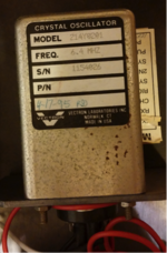
All units have a 6.4MHz reference oscillator. This is divided by 512 to get 12.5 KHz, which is the reference frequency in the PLLs. Two different types of oscillator have been found, one is a large .1 ppm unit, and the other which is a 2ppm ICM unit. The ICM unit may be non-standard or a hack, I’ve not seen enough units to be sure.
In the case of the smaller oscillator you can move it inside the TX strip case, the larger one needs to stay in place.
TX strip modifications
