Difference between revisions of "XTL Radio"
| (4 intermediate revisions by the same user not shown) | |||
| Line 69: | Line 69: | ||
|26||SPKR||Speaker - | |26||SPKR||Speaker - | ||
|} | |} | ||
| + | |||
| + | == My connections == | ||
| + | |||
| + | The below is how the XTL's installed in my vehicle are connected: | ||
| + | |||
| + | 26,20 - speaker | ||
| + | 14-15 - Jumper for Emergency | ||
| + | 7 - USB + (Green) | ||
| + | 6 - USB - (White) | ||
| + | 1 - USB Ground (Black) | ||
| + | 12 - USB 5V (Red) | ||
| + | 25 - Ignition Sense | ||
| + | |||
| + | Control Head: | ||
| + | Red - Constant 12v | ||
| + | Yellow - Ignition 12v | ||
| + | Black - Ground | ||
| + | |||
== Sourcing of connector == | == Sourcing of connector == | ||
| Line 123: | Line 141: | ||
Pictures of the XTL Accessory Connector - 027.JPG | Pictures of the XTL Accessory Connector - 027.JPG | ||
</gallery> | </gallery> | ||
| + | |||
| + | = Global Core Accessory Interface ("GCAI") = | ||
| + | |||
| + | This is the connector used for mic jacks and such. It's also used to keyload on the brick (remote mount) or via the control head (dash mount). | ||
| + | |||
| + | [[File:GCAI Connector both.png|thumb|center|GCAI Connector both]] | ||
| + | |||
| + | == GCAI Pinout == | ||
| + | |||
| + | {| class="wikitable" style="background-color:#D6DCE4; width: 60%;" | ||
| + | | colspan="6" style="text-align:Center" | '''<u>CGAI Pin Functions</U>''' | ||
| + | |- style="background-color:#D6DCE4;border-bottom:solid 2px;font-weight: bold;" | ||
| + | |rowspan=2| Pin || colspan="2" |Signal Name|| rowspan="2" | Description || rowspan="2"| RJ-45 Pin || rowspan="2" | Color | ||
| + | |--style="background-color:#EDEDED; | ||
| + | |Control Head (J1)||TIB (J700) | ||
| + | |--style="background-color:#FFFFFF; | ||
| + | |1||One-wire||One-wire|| Signal used to identify accessory.|| 3 || style="color:Orange;"| Orange | ||
| + | |--style="background-color:#FFFFFF; | ||
| + | |2||PTT||AUX-PTT|| Active low Push-to-talk input. Asserting this input on the TIB results in auxiliary microphone input use (GCAI pin 7).|| 5 || style="color:Brown;"| Brown | ||
| + | |--style="background-color:#FFFFFF; | ||
| + | |3||SPK||NC|| Receive audio out designed to drive a 150Ω load.|| NC || style="color:BLACK;"| NC | ||
| + | |--style="background-color:#FFFFFF; | ||
| + | |4||USB_D-/RS232_RX||Mid-power: RS232_RX only <br> <br> High-power: USB- / RS232_RX|| Multiplexed USB D- and RS232 receive signal. Mid-power transceivers do not support USB at the TIB GCAI connector. The RS232 signals are CMOS levels, 0-5 volts.|| 8 || style="color:BLACK;"| White | ||
| + | |--style="background-color:#FFFFFF; | ||
| + | |5||Ground||Ground|| Ground|| 2 || style="color:BLACK;"| Black | ||
| + | |--style="background-color:#FFFFFF; | ||
| + | |6||VBUS / OPT_5V||VBUS / OPT_5V|| On the control head, when the GCAI port is configured as a device, this is the VBUS input used for enumeration. When the GCAI port is configured as a host, this is the VBUS output, capable of sourcing 500mA. The TIB GCAI port can not be configured as a USB host.|| 1 || style="color:Red;"| Red | ||
| + | |--style="background-color:#FFFFFF; | ||
| + | |7||MIC_HI||AUX_MIC|| Microphone input.|| 4 || style="color:blue;"| Blue | ||
| + | |--style="background-color:#FFFFFF; | ||
| + | |8||USB_D+/RS232_TX||Mid-power: RS232_TX only <br><br> High-power: USB+ / RS232_TX|| Multiplexed USB D+ and RS232 transmit signal. The interface used is based on a one-wire read of the connected accessory. Mid-power transceivers do not support USB at the TIB GCAI connector. The RS232 signals are CMOS levels, 0-5 volts|| 7 || style="color:green;"| Green | ||
| + | |--style="background-color:#FFFFFF; | ||
| + | |9||HUB / KEYFAIL||KEYFAIL|| Multiplexed HUB and KEYFAIL lines on the control head. The TIB only has KEYFAIL.|| 6 || style="color:Yellow;"| Yellow | ||
| + | |--style="background-color:#FFFFFF; | ||
| + | |10||GPIO_0 / PWR_ON||GPIO_0|| On the control head, this pin can be used by an accessory to turn the system on.|| 2 || style="color:BLACK;"| Black | ||
| + | |} | ||
| + | |||
| + | Thoughts, it's likely that you can use the mic cable as a keyload cable. Looks like you'd need a RJ-45 jack and to plug into the TIB directly with it. Since it's multiplexed on the control head, it likely needs something to bring that to the right state. | ||
| + | |||
| + | = Operational notes = | ||
| + | |||
| + | The 900 MHz radio has an option for the pre-amp, you want this enabled. | ||
| + | |||
| + | The other concern for 900 MHz was the preselector B7250, and it's the same device from the MCS2000. Motorola describes it as a 6 MHz wide unit centered on 938 MHz, and then another follow the pre-amp for an image filter. In testing with a tracking generator it was found roll-off didn't happen until about 915 MHz and 960 MHz. This should be (and is) a fine ham band receiver. | ||
| + | |||
| + | The programing info for modifying CPS to program the hamband is on the [[XTS 2500]] page. | ||
| + | |||
= Pictures of Radios = | = Pictures of Radios = | ||
| Line 216: | Line 281: | ||
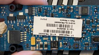
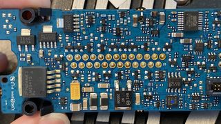
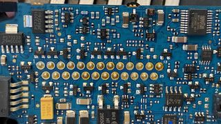
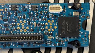
== Mid Power Flex detail == | == Mid Power Flex detail == | ||
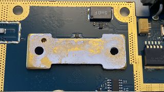
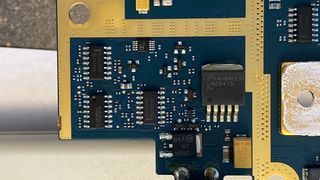
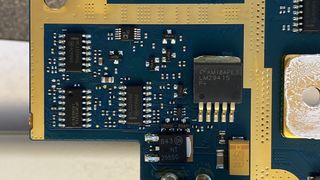
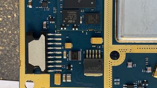
| − | <gallery> | + | <gallery mode=packed-hover> |
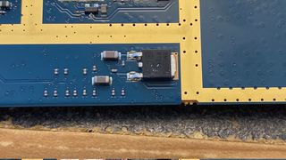
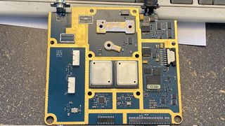
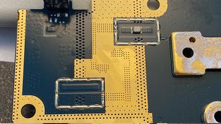
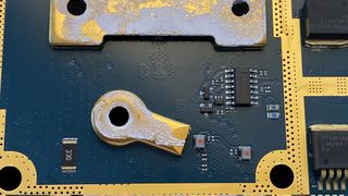
XTL_Mid-power_Flex-00001.JPG | XTL_Mid-power_Flex-00001.JPG | ||
XTL_Mid-power_Flex-00002.JPG | XTL_Mid-power_Flex-00002.JPG | ||
| Line 222: | Line 287: | ||
XTL_Mid-power_Flex-00004.JPG | XTL_Mid-power_Flex-00004.JPG | ||
</gallery> | </gallery> | ||
| − | |||
| − | |||
= Manuals = | = Manuals = | ||
Latest revision as of 16:06, 3 March 2021
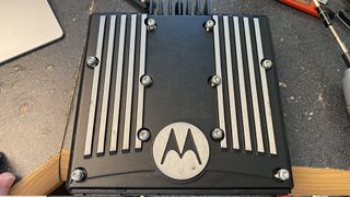
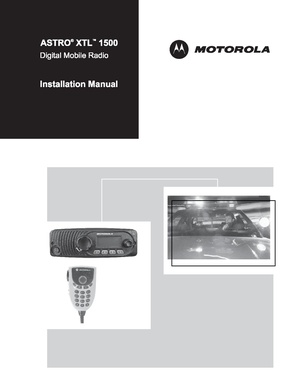
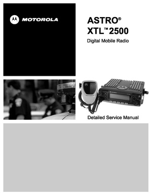
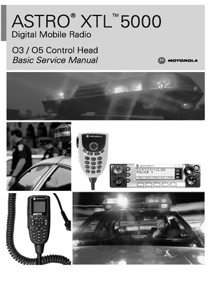
Page covering the XTL 1500/2500/5000 Radios
These are P25 trunking radios which are mono-band.
Contents
Accessory Connector
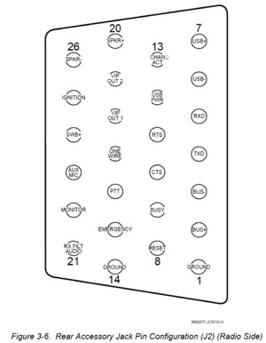
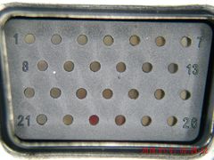
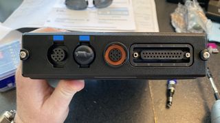
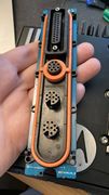
J2 is the accessory connector
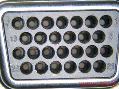
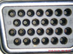
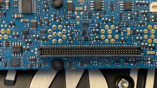
Here's a picture of it from the radio side
Table of Pins
| Rear Accessory Jack Pin Functions | ||
| Pin | Name | Function |
| 1 | GRND | Ground |
| 2 | BUS+ | SB9600 BUS+ Data |
| 3 | BUS1 | SB9600 BUS- Data |
| 4 | TXD | RS232 Transmit Data |
| 5 | RXD | RS232 Recieve Data |
| 6 | USB- | USB - (White) |
| 7 | USB+ | USB + (Green) |
| 8 | RESET | SB9600 Reset |
| 9 | BUSY | SB9600 BUSY |
| 10 | CTS | RS232 Clear to Send |
| 11 | RTS | RS232 Request to Send |
| 12 | USB PWR | USB Power +5v |
| 13 | CHAN ACT | Chanel Activity (COR+PL |
| 14 | GRND | Ground |
| 15 | EMERGENCY | Emergency |
| 16 | PTT | Push to Talk |
| 17 | ONE WIRE | One-Wire Data |
| 18 | VIP OUT 1 | Vehicular Interface Output 1 |
| 19 | VIP OUT 2 | Vehicular Interface Output 2 |
| 20 | SPKR+ | Speaker+ |
| 21 | RX FILT AUDIO | Receive Filtered Audio Out |
| 22 | Monitor | Monitor Overrides PL |
| 23 | AUX MIC | Rear Mic Input |
| 24 | SW B+ | Switched Battery Voltage |
| 25 | IGN | Ignition Sense |
| 26 | SPKR | Speaker - |
My connections
The below is how the XTL's installed in my vehicle are connected:
26,20 - speaker
14-15 - Jumper for Emergency
    7 - USB + (Green)
    6 - USB - (White)
    1 - USB Ground (Black)
   12 - USB 5V (Red)
   25 - Ignition Sense

Control Head:
Red - Constant 12v
Yellow - Ignition 12v
Black - Ground
Sourcing of connector
As of now, there is no other source for the connector than Motorola. The rumor mill puts money on ITT Canon being the manufacturer.
The pins come in a 25 pin strip Motorola Part Number: 3980034F05
The housings are HLN6961
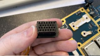
The body looks like 2 D-Sub connectors stacked with standard pitch spacing on the pins.
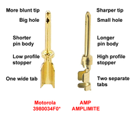
Aftermarket Pins will not work due to the low profile retaining ring. This thread on the Batlabs Batboard has some more info and this picture showing the differences below:
Notes on assembly
The TE 91285-1 Pin extraction tool is highly recommended. DigiKey Link
The Engineer PA-09 is recommenced as a crimper.
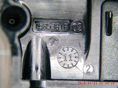
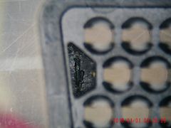
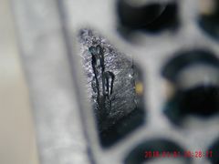
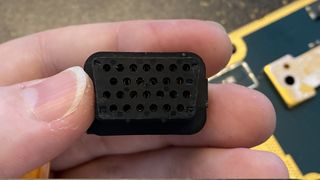
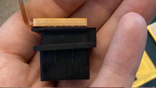
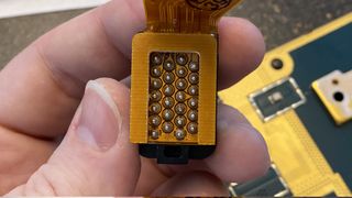
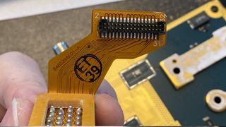
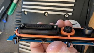
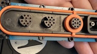
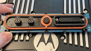
Photos of connector
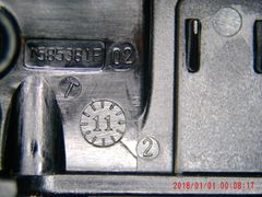
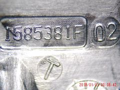
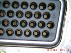
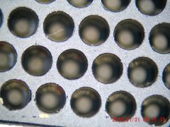
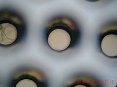
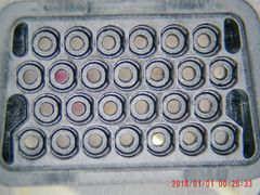
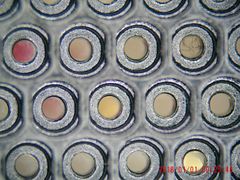
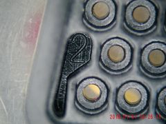
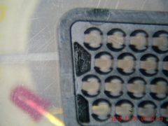
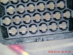
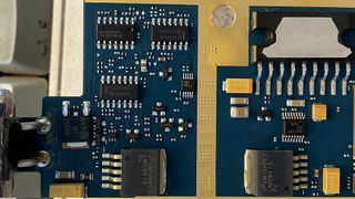
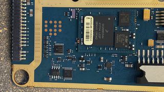
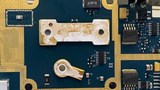
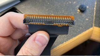
I disassembled and took some close up pictures with my scope. The connector looks a bit similar to most D-SUB connectors.
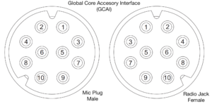
Global Core Accessory Interface ("GCAI")
This is the connector used for mic jacks and such. It's also used to keyload on the brick (remote mount) or via the control head (dash mount).
GCAI Pinout
| CGAI Pin Functions | |||||
| Pin | Signal Name | Description | RJ-45 Pin | Color | |
| Control Head (J1) | TIB (J700) | ||||
| 1 | One-wire | One-wire | Signal used to identify accessory. | 3 | Orange |
| 2 | PTT | AUX-PTT | Active low Push-to-talk input. Asserting this input on the TIB results in auxiliary microphone input use (GCAI pin 7). | 5 | Brown |
| 3 | SPK | NC | Receive audio out designed to drive a 150Ω load. | NC | NC |
| 4 | USB_D-/RS232_RX | Mid-power: RS232_RX only High-power: USB- / RS232_RX |
Multiplexed USB D- and RS232 receive signal. Mid-power transceivers do not support USB at the TIB GCAI connector. The RS232 signals are CMOS levels, 0-5 volts. | 8 | White |
| 5 | Ground | Ground | Ground | 2 | Black |
| 6 | VBUS / OPT_5V | VBUS / OPT_5V | On the control head, when the GCAI port is configured as a device, this is the VBUS input used for enumeration. When the GCAI port is configured as a host, this is the VBUS output, capable of sourcing 500mA. The TIB GCAI port can not be configured as a USB host. | 1 | Red |
| 7 | MIC_HI | AUX_MIC | Microphone input. | 4 | Blue |
| 8 | USB_D+/RS232_TX | Mid-power: RS232_TX only High-power: USB+ / RS232_TX |
Multiplexed USB D+ and RS232 transmit signal. The interface used is based on a one-wire read of the connected accessory. Mid-power transceivers do not support USB at the TIB GCAI connector. The RS232 signals are CMOS levels, 0-5 volts | 7 | Green |
| 9 | HUB / KEYFAIL | KEYFAIL | Multiplexed HUB and KEYFAIL lines on the control head. The TIB only has KEYFAIL. | 6 | Yellow |
| 10 | GPIO_0 / PWR_ON | GPIO_0 | On the control head, this pin can be used by an accessory to turn the system on. | 2 | Black |
Thoughts, it's likely that you can use the mic cable as a keyload cable. Looks like you'd need a RJ-45 jack and to plug into the TIB directly with it. Since it's multiplexed on the control head, it likely needs something to bring that to the right state.
Operational notes
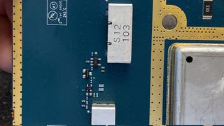
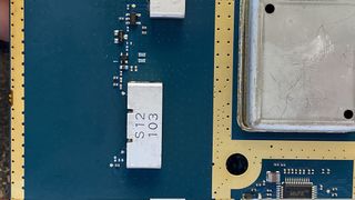
The 900 MHz radio has an option for the pre-amp, you want this enabled.
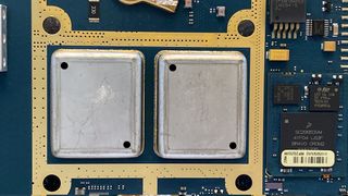
The other concern for 900 MHz was the preselector B7250, and it's the same device from the MCS2000. Motorola describes it as a 6 MHz wide unit centered on 938 MHz, and then another follow the pre-amp for an image filter. In testing with a tracking generator it was found roll-off didn't happen until about 915 MHz and 960 MHz. This should be (and is) a fine ham band receiver.
The programing info for modifying CPS to program the hamband is on the XTS 2500 page.
Pictures of Radios
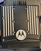
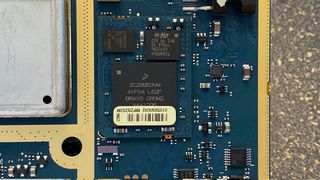
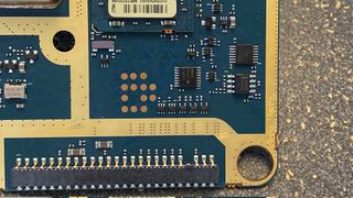
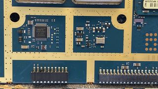
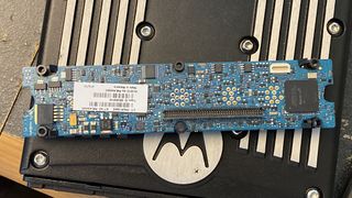
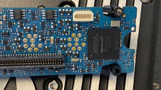
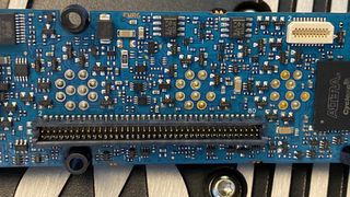
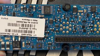
Brick and TIB
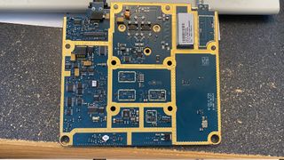
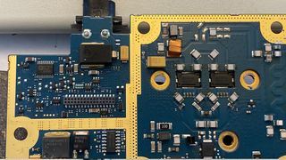
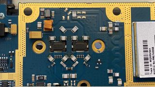
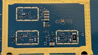
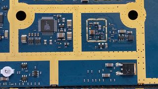
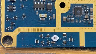
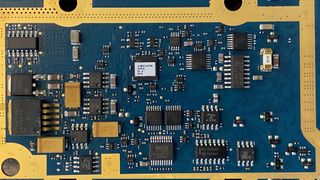
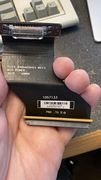
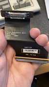
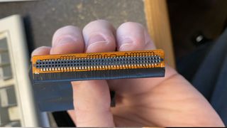
TIB
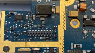
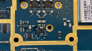
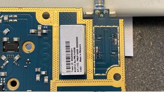
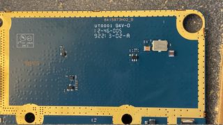
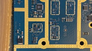
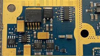
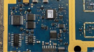
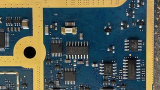
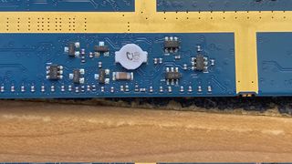
Control Head Interface
