Difference between revisions of "2020 Ram 1500 Radio Install"
| Line 80: | Line 80: | ||
Test Fit Radios00002.JPG | Test Fit Radios00002.JPG | ||
Radios mounted on board.JPG | Radios mounted on board.JPG | ||
| + | </gallery> | ||
| + | |||
| + | The main #4 power cables were brought out to the bus bars I got from amazon. These were screwed into the floor metal under the carpet where there was a "hump" or free space. Importantly the negative cable was brought to the chassis ground before the bus bar to prevent a floating ground. The connectors were coated with silicone lube for good measure. In the future should an additional radio or connection need to be made, this provides a high amperage point to connect to. | ||
| + | |||
| + | <gallery widths=300pm heights=300px mode=packed> | ||
| + | Back Wireing00001.JPG | ||
| + | Back Wireing00002.JPG | ||
| + | </gallery> | ||
| + | |||
| + | As I wasn't going to have good access the the radios, I made up cable harness for them with built in programing cables. | ||
| + | |||
| + | <gallery widths=300pm heights=300px mode=packed> | ||
| + | XTL Cable harness 00001.JPG | ||
| + | XTL Cable harness 00002.JPG | ||
</gallery> | </gallery> | ||
Revision as of 04:57, 18 October 2020
I purchased a 2020 Ram 1500 Limited Ecodiesel, and have struggled to install a professional looking radio install in it. I don't want to have anything that would damage the vehicle (no bolts in the dash, etc.). Making it much more difficult is the vehicle is not really something which would be up-fitted with radios or lights for commercial use at this trim level. There's a 12" display and leather everywhere, so discreetly drilling a mount it will not be possible.
Radios to install
- 220 MHz Motorola CDM "1850" with remote head
- 440 MHz Motorola XTL2500 with O5 remote head
- 900 MHz Motorola XTL2500 with O3 Hand Held Control Head (HHCH)
- Blackview Dashcam
Goals for install
- Ignition sense for turning radios on/off
- Minimum impact to vehicle
- remote mount
- Single Speaker - this means a mixer will be built
- power directly from battery
- everything must enable expansion
Contents
Install Parts
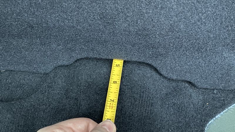
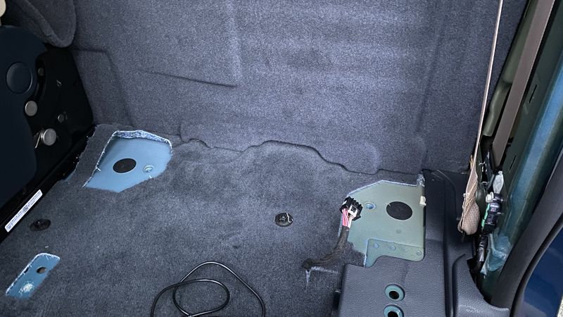
I decided to locate the radio decks on the rear drivers side wall of the truck. There is an ecoboost version of the gas engine which has an electric assist or some such thing. This means there's a large 48v battery pack located behind the rear drivers side seat in the cab. This is just over 6" of depth behind the seats, perfect for mounting radios.
Battery
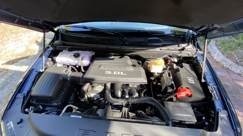
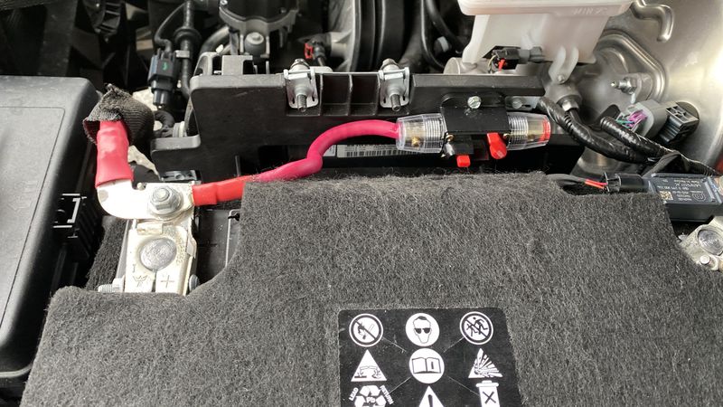
I decided to run a #2 wire to the battery via a 100 amp breaker. Welding cable was sourced from Skycraft Surplus in Orlando, along with lugs and such.
There's an easy to access rubber feed through grommet that fit the cables once a hole was poked through it. I only fused the positive side, as the negative will be tied to the ground in the rear of the cab. I bought 35' of cable, but only needed about 20', better to have too much than too little.
Ignition sense
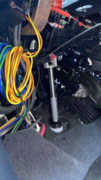
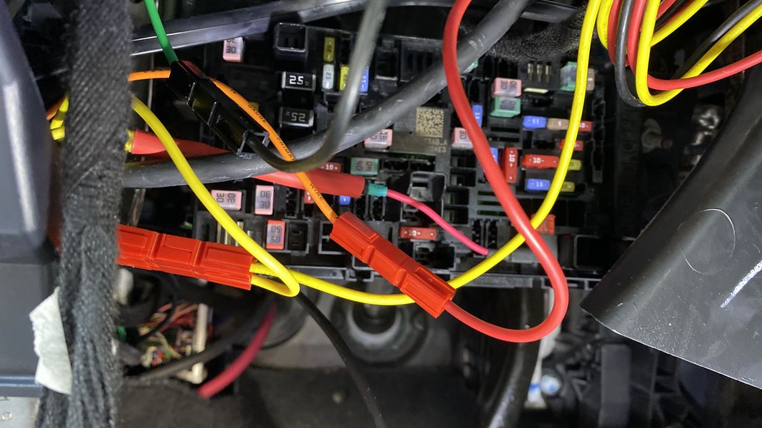
The ignition sense was installed with a fuse tap in position 66 of the fuse block on the drivers side under the steering wheel. This was fused with a 5a fuse and I connected 3 power pole connectors to the output. One goes to the rear, one to the O5 head in the center console, and one is a spare. I used a lug with 4 black power poles as a ground point for the control heads too. This lug was installed on a 10mm bolt holding the fuse panel up. It tested to be a good ground point.
- Yellow wire is the ignition sense
- Red wire is B+ from back for control head.
- Blue and Green are unused
Rear Area
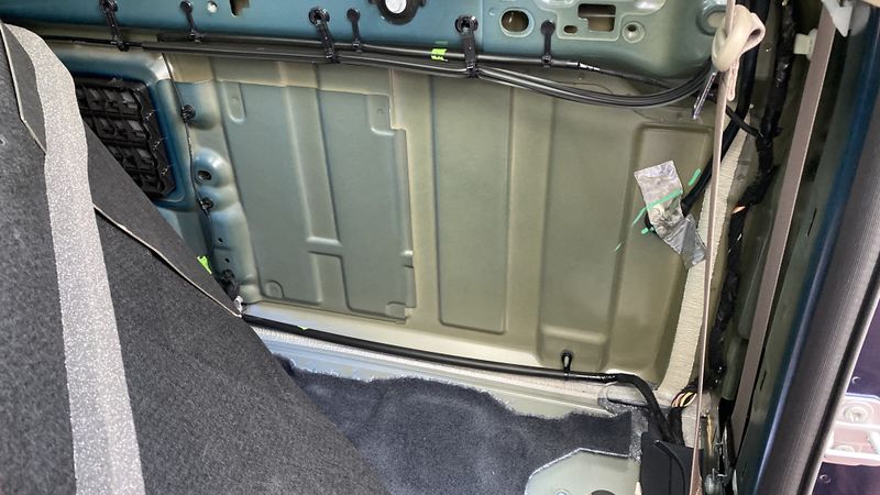
The decision was made to mount the radio to the rear wall of the cab behind the drivers rear seat. There was about 5" of room open here. The seat was easy to remove with a 14mm driver and a star driver.
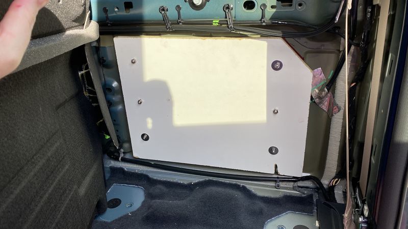
I didn't want to drill holes through the rear cab wall for mounting the radio brackets due to weather proofing and rust issues. It occurred that mounting to a MDF board would work as I had the depth to work with. I would need a bracket to hold the board to the wall, something that would be removable even with the seat installed as I didn't want to have to remove the seat to service the radios.
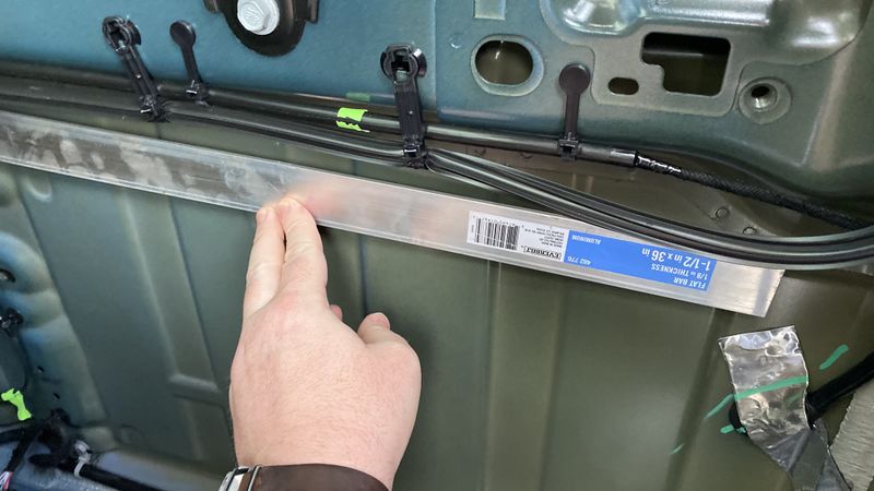
My first idea was to make some brackets out of flat aluminum stock and bolts, but there was no easy way to secure the bolts to the stock as the bolts were stainless.
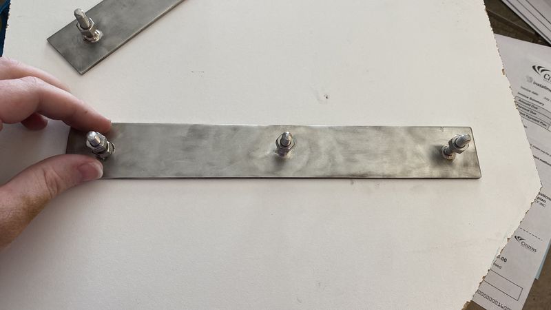
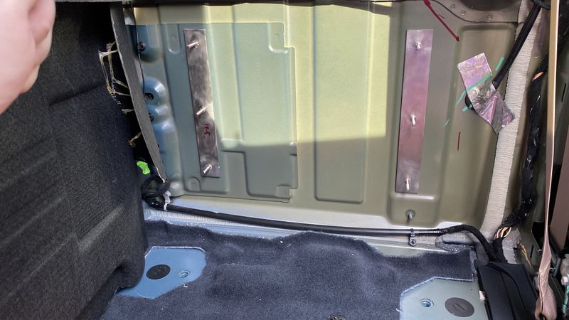
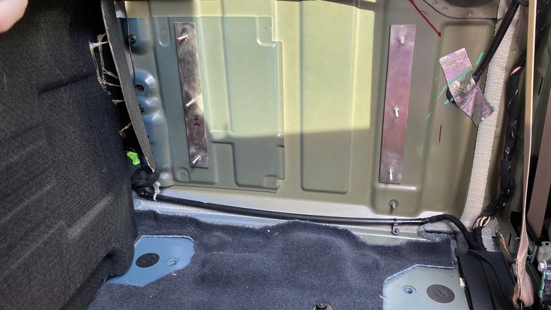
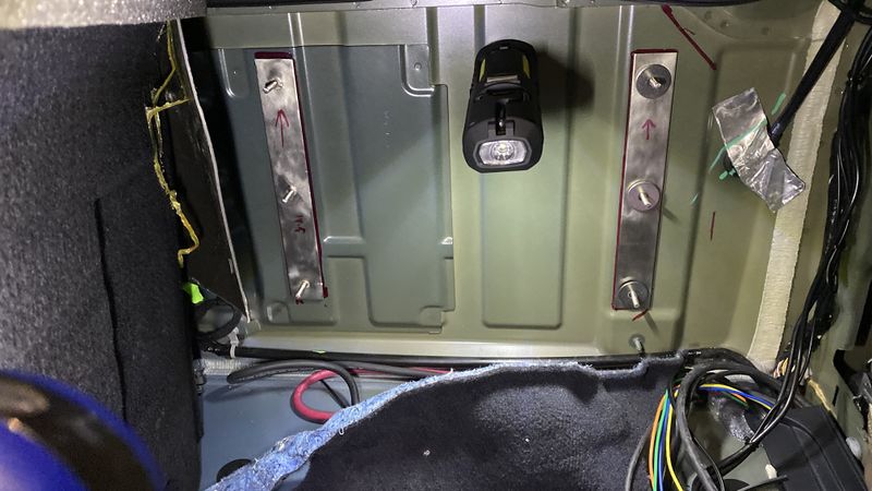
I moved to Stainless flat bar stock and used some 56% silver brazing rods to weld in 1/4" bolts. I mounted the brackets to the cab wall with 3M double sided tape. It's a concern this might fail, and if it does, I will upgrade to epoxy. I'd like to easily remove the brackets if I want to sell in the future.
- SS brackets 02.JPG
- SS brackets 03.JPG
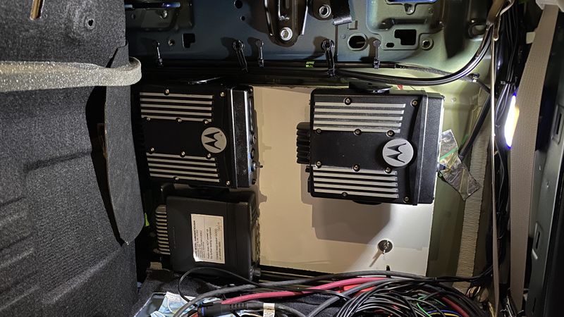
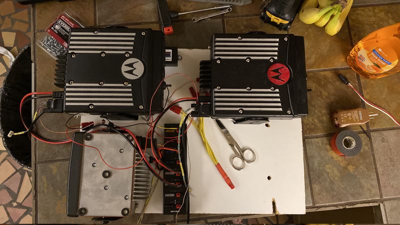
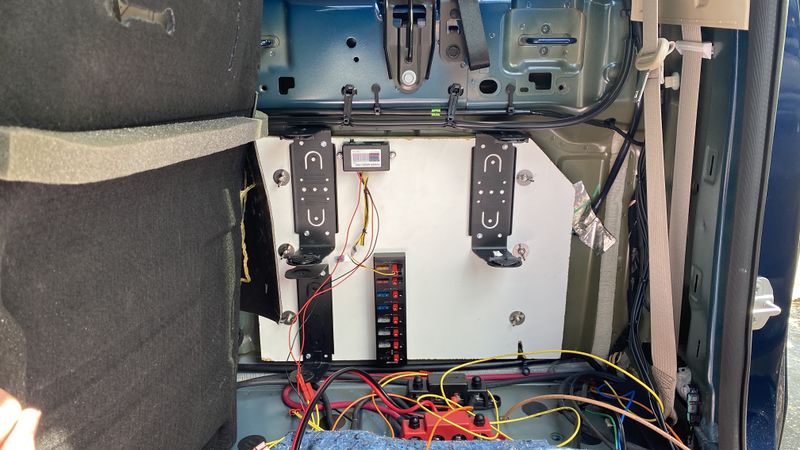
After this I cut some MDF board to fit and drilled it. Using wing nuts to secure it and some backing washers to level it out (the rear wall was not level between the brackets). I test fit the radios on the board to see it fit would hold. The red radio is the 900 and I also installed a 40 A powerpole fuse center too. I left space open for another radio.
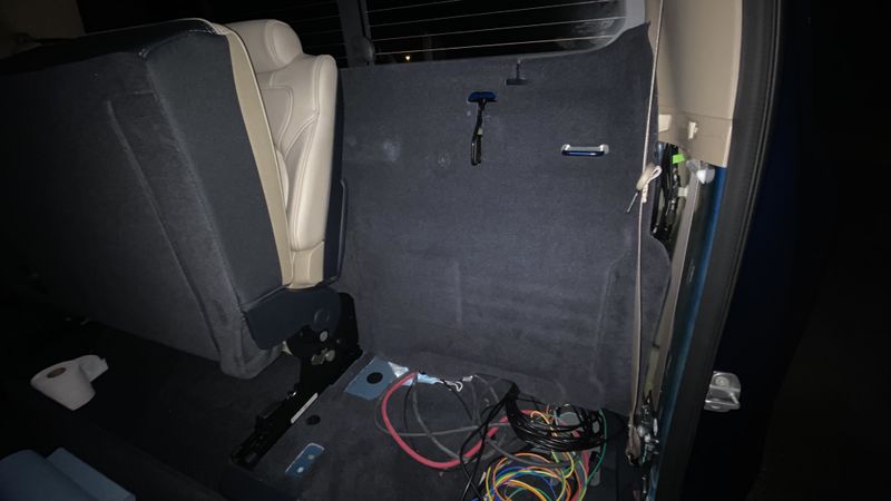
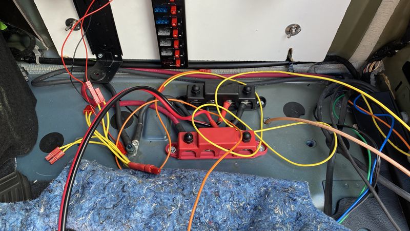
The main #4 power cables were brought out to the bus bars I got from amazon. These were screwed into the floor metal under the carpet where there was a "hump" or free space. Importantly the negative cable was brought to the chassis ground before the bus bar to prevent a floating ground. The connectors were coated with silicone lube for good measure. In the future should an additional radio or connection need to be made, this provides a high amperage point to connect to.
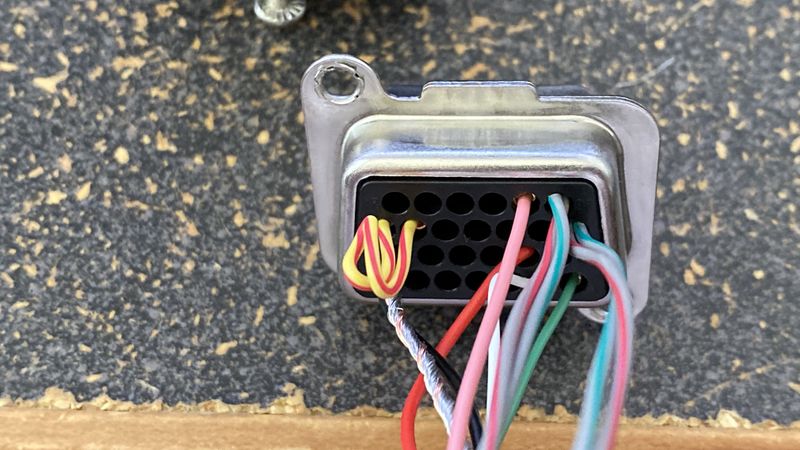
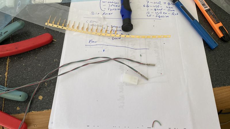
As I wasn't going to have good access the the radios, I made up cable harness for them with built in programing cables.
