XTS Keyboard/UCM
The XTS series have a Universal Crypto Module (UCM) and Keyboard/option board combo. Normally without hardware crypto, they will have the keyboard only option board, and the part numbers vary base on the model type (1.5,2,3).
Contents
Model Matrix
| XTS2500 Keypads | ||||
|---|---|---|---|---|
| P/N | TYPE | Model | BackLight | Description |
| 0104018J69 | 1.5 | Keypad | Bright | Motorola Part from Service Manual, no crypto |
| 7585776C02 | 2 | Keypad | Bright | Motorola Part from Service Manual, no crypto |
| 7585776C01 | 3 | Keypad | Bright | Motorola Part from Service Manual, no crypto |
| 0104020J49 | 1.5 | Kit, FM | Bright | This is a listed accessory kit |
| 0104020J50 | 2 | Kit, FM | Bright | This is a listed accessory kit |
| 0104020J51 | 3 | Kit, FM | Bright | This is a listed accessory kit |
| 0104024J45 | 1.5 | Unknown | Bright | 5 Algo, From an eBay auction |
| 0104024J44 | 2? | Unknown | Bright | Never seen this, inferred as model 2 |
| 0104024J43 | 3 | Unknown | Bright | 5 Algo, From an eBay auction |
| 0104027J01 | 1.5? | US Military | Dim | Never seen this, inferred as model 1.5 Night Vision |
| 0104025J11 | 2? | US Military | DIM | Never seen this, inferred as model 2 Night Vision |
| 0104025J12 | 3 | US Military | Dim | AES only, Night Vision, from a Facebook seller |
The above crypto parts are listed in the "Security Policy:Astro Subscriber UCM" Guide. Some part descriptions are an inference on my part as I've not seen them, they are designated with a ?. If something is wrong, please update it.
It's my understanding any of the UCM's can do any algorithms, they just need to be programed via a KVL3000+ or later keyloader.
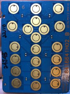
The different model UCM's are the same, but lacking the Snaptron keys and polyester tape to hold them in. The LED's are missing in the 1.5 version as well, but the dropping resistors are present. This is due to the backlight for the LCD being sourced from the keypad. The CPU will simply tell the Keypad backlight on, and the keypad will take care of the rest.
Note the dim listed parts are for use with night vision, and will appear to be not working in daylight and barely visible at night. I've experimented with these and have reverse engineered a better soultion below.
There is a connector on the bottom of the board that looks about the same and will mate with the LCD connector. I suspect this is used to load the boot firmware on the UCM at the factory. It may be possible to restore a UCM via this connector in case of failed upgrades.
Pictures of UCM's
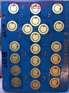
0104025J12 back
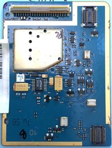
0104024J45 Front
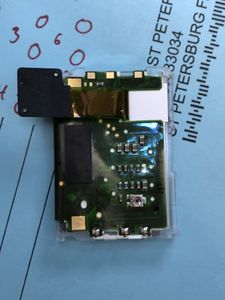
XTS2500 LCD module
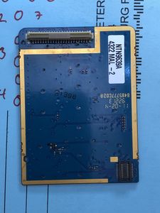
7585776C01 Back
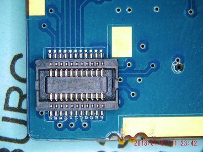
XTS2500 LCD connector
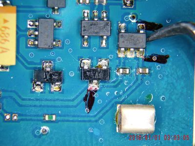
XTS2500 0104025J12 DIM UCM 5v regulator


Notes on UCM parts
The UCM has no diagrams for it, and perhaps one of the most frustrating issues is having a working UCM, but broken connector. The connector is a Hirose FH12-45S-0.5SVA(54). This is Digi-Key Par Number H125151CT-ND.
The LED's are 0402, and I have some ideas on replacement.
The key caps are likely a P27220 from Snaptron.
Modification of Dim to Normal
There are a few UCM boards made for night vision equipment, and I reversed how to make these brighter by studying a couple good boards. It's basically some current limiting resistors and a regulator. In the dim UCM there is an addition of a 5v regulator which powers the LEDs rather than being powered via the B+ voltage of 7.5 volts.
I've reverse engineered the partial diagram of the dim UCM below. It's also available as a pdf.

First the MAX1615 5v regulator needs to be removed and jumpered out. This will put B+ (7.5v) on the LED's vs 5v.
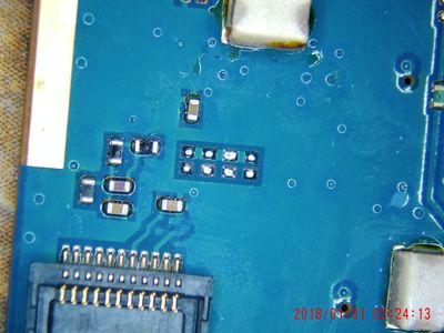
The following resistors need to be changed, note they are 0402 size parts:
| LED resistors | ||
| Number | Dim | Bright |
| R18 | 560 | 330 |
| R27 | 560 | 330 |
| R63 | 560 | 330 |
| R45 | 560 | 330 |
| R9 | 6800 | 560 |
| R10 | 6800 | 560 |
| R11 | 6800 | 560 |
| R12 | 6800 | 560 |
I've experimented and most of the improvement comes from changing the LCD resistors (R9-R12). The difference of the limiting resistors on the keypad LED's is not as noticeable as the 5 to 7.5v on them.
The UCM is a well shielded multi-layer board and you will need a good size board preheater and hot air station to get the IC and resistors to come off the board. Go slow and it will come up. Don't worry much about melting the tape holding the snapkeys to the front, as it's a high temperature polyester material.
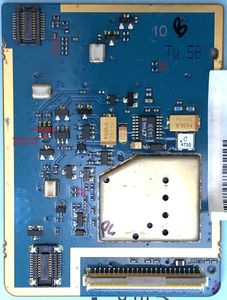
UCM Back resistor locations
UCM front LED locations
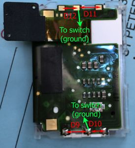
XTS2500 LCD board LED locations
XTS2500 0104025J12 DIM UCM 5v regulator
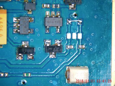
UCM Mod 5 volt regulator jumpered
XTS2500 LCD LED resistors


Notes
I've been informed there is another modification out there being sold. This modification simply jumpers the B+ to the 5v output of the regulator. This means whenever the backlight is on the regulator is going to be fighting and possibly overheating. The regulator is going to burn up eventually and/or the flex cables will overheat. I've measured upwards of an 1200 ma of current draw when the backlight is on in these improperly modified radios.
Video
I have a video of this up here on youtube.