Difference between revisions of "XTL Radio"
Jump to navigation
Jump to search
| Line 11: | Line 11: | ||
== Table of Pins == | == Table of Pins == | ||
| + | |||
| + | {| class="wikitable" style="background-color:#D6DCE4; width: 60%;" | ||
| + | | colspan="3" style="text-align:Center" | '''<u>Rear Accessory Jack Pin Functions</U>''' | ||
| + | |- style="background-color:#D6DCE4;border-bottom:solid 2px;font-weight: bold;" | ||
| + | | Pin ||Name||Function | ||
| + | |--style="background-color:#EDEDED; | ||
| + | |1||GRND||Ground | ||
| + | |--style="background-color:#EDEDED; | ||
| + | |2||BUS+||SB9600 BUS+ Data | ||
| + | |--style="background-color:#EDEDED; | ||
| + | |3||BUS1||SB9600 BUS- Data | ||
| + | |--style="background-color:#EDEDED; | ||
| + | |4||TXD||RS232 Transmit Data | ||
| + | |--style="background-color:#EDEDED; | ||
| + | |5||RXD||RS232 Recieve Data | ||
| + | |--style="background-color:#EDEDED; | ||
| + | |6||USB-||USB - (White) | ||
| + | |--style="background-color:#EDEDED; | ||
| + | |7||USB+||USB + (Green) | ||
| + | |--style="background-color:#EDEDED; | ||
| + | |8||RESET||SB9600 Reset | ||
| + | |--style="background-color:#EDEDED; | ||
| + | |9||BUSY||SB9600 BUSY | ||
| + | |--style="background-color:#EDEDED; | ||
| + | |10||CTS||RS232 Clear to Send | ||
| + | |--style="background-color:#EDEDED; | ||
| + | |11||RTS||RS232 Request to Send | ||
| + | |--style="background-color:#EDEDED; | ||
| + | |12||USB PWR|| USB Power +5v | ||
| + | |--style="background-color:#EDEDED; | ||
| + | |13||CHAN ACT|| Chanel Activity (COR+PL | ||
| + | |--style="background-color:#EDEDED; | ||
| + | |14||GRND||Ground | ||
| + | |--style="background-color:#EDEDED; | ||
| + | |15||EMERGENCY||Emergency | ||
| + | |--style="background-color:#EDEDED; | ||
| + | |16||PTT||Push to Talk | ||
| + | |--style="background-color:#EDEDED; | ||
| + | |17||ONE WIRE||One-Wire Data | ||
| + | |--style="background-color:#EDEDED; | ||
| + | |18||VIP OUT 1||Vehicular Interface Output 1 | ||
| + | |--style="background-color:#EDEDED; | ||
| + | |19||VIP OUT 2||Vehicular Interface Output 2 | ||
| + | |--style="background-color:#EDEDED; | ||
| + | |20||SPKR+|| Speaker+ | ||
| + | |--style="background-color:#EDEDED; | ||
| + | |21||RX FILT AUDIO|| Receive Filtered Audio Out | ||
| + | |--style="background-color:#EDEDED; | ||
| + | |22||Monitor||Monitor Overrides PL | ||
| + | |--style="background-color:#EDEDED; | ||
| + | |23||AUX MIC||Rear Mic Input | ||
| + | |--style="background-color:#EDEDED; | ||
| + | |24||SW B+||Switched Battery Voltage | ||
| + | |--style="background-color:#EDEDED; | ||
| + | |25||IGN||Ignition Sense | ||
| + | |--style="background-color:#EDEDED; | ||
| + | |26||SPKR||Speaker - | ||
== Sourcing of connector == | == Sourcing of connector == | ||
Revision as of 01:09, 12 May 2020
Page covering the XTL 1500/2500/5000 Radios
These are P25 trunking radios which are mono-band.
Contents
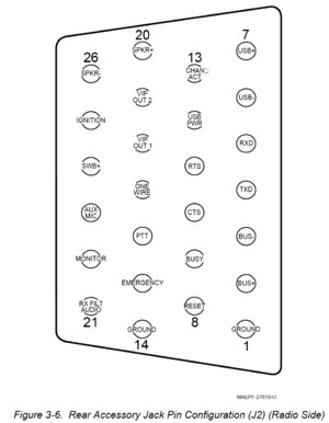
Accessory Connector
J2 is the accessory connector
Here's a picture of it from the radio side

Table of Pins
| Rear Accessory Jack Pin Functions | ||
| Pin | Name | Function |
| 1 | GRND | Ground |
| 2 | BUS+ | SB9600 BUS+ Data |
| 3 | BUS1 | SB9600 BUS- Data |
| 4 | TXD | RS232 Transmit Data |
| 5 | RXD | RS232 Recieve Data |
| 6 | USB- | USB - (White) |
| 7 | USB+ | USB + (Green) |
| 8 | RESET | SB9600 Reset |
| 9 | BUSY | SB9600 BUSY |
| 10 | CTS | RS232 Clear to Send |
| 11 | RTS | RS232 Request to Send |
| 12 | USB PWR | USB Power +5v |
| 13 | CHAN ACT | Chanel Activity (COR+PL |
| 14 | GRND | Ground |
| 15 | EMERGENCY | Emergency |
| 16 | PTT | Push to Talk |
| 17 | ONE WIRE | One-Wire Data |
| 18 | VIP OUT 1 | Vehicular Interface Output 1 |
| 19 | VIP OUT 2 | Vehicular Interface Output 2 |
| 20 | SPKR+ | Speaker+ |
| 21 | RX FILT AUDIO | Receive Filtered Audio Out |
| 22 | Monitor | Monitor Overrides PL |
| 23 | AUX MIC | Rear Mic Input |
| 24 | SW B+ | Switched Battery Voltage |
| 25 | IGN | Ignition Sense |
| 26 | SPKR | Speaker -
Sourcing of connectorAs of now, there is no other source for the connector than Motorola. The body looks like 2 D-Sub connectors stacked with standard pitch spacing on the pins. Aftermarket Pins will not work due to the low profile retaining ring. This thread on the Batlabs Batboard has some more info and this picture showing the differences below: Photos of connectorI disassembled and took some close up pictures with my scope. The connector looks a bit similar to most D-SUB connectors. Manuals |