Difference between revisions of "800 MHz Receiver"
(→Basics) |
|||
| (12 intermediate revisions by the same user not shown) | |||
| Line 5: | Line 5: | ||
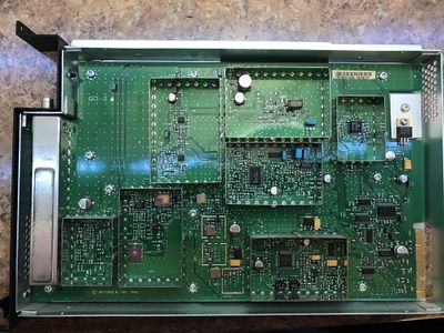
The receiver is pictured below. The 800/900 receiver differs from all others as it's half width and includes an internal preselector. The preselector is soldered on to the board and not tune-able as in the VHF/UHF modules. | The receiver is pictured below. The 800/900 receiver differs from all others as it's half width and includes an internal preselector. The preselector is soldered on to the board and not tune-able as in the VHF/UHF modules. | ||
| − | <gallery heights="200px" widths="200px" mode="packed"> | + | <gallery heights="200px" widths="200px" mode="packed-hover"> |
800 MHz Receiver - 0241.JPG|800 MHz Receiver - 0241 | 800 MHz Receiver - 0241.JPG|800 MHz Receiver - 0241 | ||
800 MHz Receiver - 0242.JPG|800 MHz Receiver - 0242 | 800 MHz Receiver - 0242.JPG|800 MHz Receiver - 0242 | ||
| Line 14: | Line 14: | ||
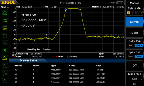
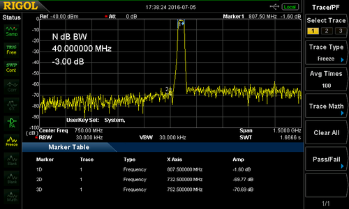
There is a 7 pole preselector in the front end prior to the first RF amplifier. This has about a 1.5 db insertion loss with a very good roll off. I'm actually surprised it's as good as it is, 1.5 dB is low for a ceramic filter. | There is a 7 pole preselector in the front end prior to the first RF amplifier. This has about a 1.5 db insertion loss with a very good roll off. I'm actually surprised it's as good as it is, 1.5 dB is low for a ceramic filter. | ||
| − | <gallery heights="200px" widths="200px" mode="packed"> | + | <gallery heights="200px" widths="200px" mode="packed-hover"> |
Quantar 800 Mhz Preelector Narrow sweep.png| Quantar 800 Mhz Preselector Narrow sweep | Quantar 800 Mhz Preelector Narrow sweep.png| Quantar 800 Mhz Preselector Narrow sweep | ||
800 MHz Quantar Receiver Preselector Wide Sweep.png| 800 MHz Quantar Receiver Preselector Wide Sweep | 800 MHz Quantar Receiver Preselector Wide Sweep.png| 800 MHz Quantar Receiver Preselector Wide Sweep | ||
| Line 23: | Line 23: | ||
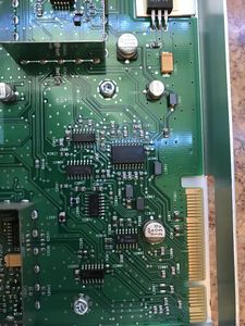
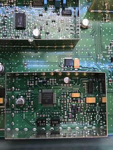
There is a image filter (FL2030) which filters the input to the double balanced mixer to prevent the RF radiating out the antenna port. | There is a image filter (FL2030) which filters the input to the double balanced mixer to prevent the RF radiating out the antenna port. | ||
| − | <gallery heights=" | + | <gallery heights="300px" widths="300px" mode="packed-hover"> |
800 MHz Receiver - Mixer filters.png | 800MHz Receiver Image Filters | 800 MHz Receiver - Mixer filters.png | 800MHz Receiver Image Filters | ||
800 MHz RX Image Filter 2.jpg| 800 MHz RX Image Filter | 800 MHz RX Image Filter 2.jpg| 800 MHz RX Image Filter | ||
| − | 800 MHz RX Image | + | 800 MHz RX Image filter 1.jpg| 800 MHz RX Image Filter |
Quantar 800 MHz Receiver Image filter response.png| FL2030 response | Quantar 800 MHz Receiver Image filter response.png| FL2030 response | ||
</gallery> | </gallery> | ||
| Line 32: | Line 32: | ||
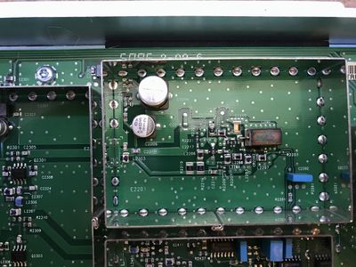
In the second 800 MHz board I looked at, (TRF6551G39) there is another filter (FL2300) which is on the input to the mixer from the Local Oscillator output. This is not present in the first board I converted (TRF6551J), and just has a 50 ohm line in place of it. It remains to be seen what this filter does. It needs to be removed and swept for response. | In the second 800 MHz board I looked at, (TRF6551G39) there is another filter (FL2300) which is on the input to the mixer from the Local Oscillator output. This is not present in the first board I converted (TRF6551J), and just has a 50 ohm line in place of it. It remains to be seen what this filter does. It needs to be removed and swept for response. | ||
| − | <gallery heights=" | + | <gallery heights="300px" widths="300px" mode="packed-hover"> |
800 MHz Receiver - Mixer filters.png|800 MHz Receiver TRF6551G39 - Image Filter | 800 MHz Receiver - Mixer filters.png|800 MHz Receiver TRF6551G39 - Image Filter | ||
800 MHz Receiver TRF6551J - 0305.JPG|800 MHz Receiver TRF6551J - Image Filter | 800 MHz Receiver TRF6551J - 0305.JPG|800 MHz Receiver TRF6551J - Image Filter | ||
| + | 800 MHz Receiver TRF6551H diagram FL2300.png|800 MHz Receiver TRF6551H diagram FL2300 | ||
</gallery> | </gallery> | ||
| Line 53: | Line 54: | ||
The VCO in the 800 differs from the 900 unit in that the 800 VCO does not have a soldered on shield over it. I'm not sure what difference this makes in practical use. Note on the TRF6551J unit there is a solder mask which would fit a shield. | The VCO in the 800 differs from the 900 unit in that the 800 VCO does not have a soldered on shield over it. I'm not sure what difference this makes in practical use. Note on the TRF6551J unit there is a solder mask which would fit a shield. | ||
| − | <gallery heights= | + | <gallery heights=300px widths=300px mode="packed-hover"> |
900 MHz RX VCO shield.jpg|900 MHz RX VCO shield | 900 MHz RX VCO shield.jpg|900 MHz RX VCO shield | ||
800 MHz Receiver - 0252.JPG|800 MHz VCO no shield | 800 MHz Receiver - 0252.JPG|800 MHz VCO no shield | ||
| Line 69: | Line 70: | ||
In PNG format. | In PNG format. | ||
| − | <gallery heights=100px widths= | + | <gallery heights=100px widths=200px mode="packed-hover"> |
800 MHz Receiver TRF6551H diagram exerpt-1.png|800 MHz Receiver Diagram 1 | 800 MHz Receiver TRF6551H diagram exerpt-1.png|800 MHz Receiver Diagram 1 | ||
800 MHz Receiver TRF6551H diagram exerpt-2.png|800 MHz Receiver Diagram 2 | 800 MHz Receiver TRF6551H diagram exerpt-2.png|800 MHz Receiver Diagram 2 | ||
| Line 78: | Line 79: | ||
== Pictures == | == Pictures == | ||
| − | <gallery heights= | + | <gallery heights=200px widths=200px mode="packed-hover"> |
800 MHz Receiver - 0245.JPG|800 MHz Receiver 1 | 800 MHz Receiver - 0245.JPG|800 MHz Receiver 1 | ||
800 MHz Receiver - 0246.JPG|800 MHz Receiver 2 | 800 MHz Receiver - 0246.JPG|800 MHz Receiver 2 | ||
| Line 101: | Line 102: | ||
= Conversions = | = Conversions = | ||
| − | Converting the | + | Converting to the 800 MHz to 900 MHz receiver works best if you plan to use an external preselector/pre-amp as the losses on 900 MHz are high. 100' of 7/8" heliax has just under 1.2 dB of loss, and 6' of RG-400 is 1 dB. It's completely possible to have 6' of interconnect cable between the duplexers and filters, and installing a pre-amp as close to the preselctor as possible will negate most of this loss. |
== 800 to 900 MHz == | == 800 to 900 MHz == | ||
| Line 107: | Line 108: | ||
The basic premise of converting the 800 to a 900 is four major parts: | The basic premise of converting the 800 to a 900 is four major parts: | ||
* Convert the VCO for the proper frequency coverage | * Convert the VCO for the proper frequency coverage | ||
| − | * Modify the | + | * Remove/Modify the ceramic preselector |
* Change the module ID | * Change the module ID | ||
| − | * | + | * Test the unit. |
| − | It's important to have a known good working unit on | + | It's important to have a known good working unit on 800 before starting work. If it is not working at it's intended frequency, fix it first. |
It would be good to become very familiar with the schematic and service manual before attempting this. | It would be good to become very familiar with the schematic and service manual before attempting this. | ||
| Line 119: | Line 120: | ||
* Hot air station | * Hot air station | ||
* Under board pre-heater | * Under board pre-heater | ||
| + | * 1000W heat gun and tips (for preselector removal) | ||
* High quality soldering iron (metcal) | * High quality soldering iron (metcal) | ||
* Dual voltage variable DC supply | * Dual voltage variable DC supply | ||
| Line 127: | Line 129: | ||
=== Converting VCO === | === Converting VCO === | ||
| − | + | There is a single VCO for both the 800 and 900 bands. This is in contrast to the UHF and VHF modules which use two VCO to cover the entire band. The VCO (Q2202) consists of a tuned coax resonator shorted on one end (L2202) in resonance with parallel capacitors (C2211 & C2209) and laser cut tuning capacitor (C2205). | |
| + | |||
| + | As this is a low side injection receiver the VCO runs 73.35 MHz below the intended signal. This is different from the high side injection systems used on VHF and UHF. Low side injection is less of an issue on 800/900 as traditionally there are no users on the image frequencies (+73 MHz) of any real ERP to cause interference. | ||
| + | |||
| + | |||
| + | |||
| + | * Mask off the VCO using Krapton tape and/or aluminum foil. The electrolytic caps don't do well with excess heat, especially as most are 10-15 years old at this point. | ||
| + | |||
| + | <gallery widths=300px heights=300px mode="packed-hover"> | ||
| + | 800 MHz Receiver vco diagram.png|800 MHz Receiver vco diagram | ||
| + | 800 MHz VCO taped off.JPG|800 MHz Receiver VCO taped off for desoldering | ||
| + | </gallery> | ||
| + | |||
| + | * Setup the board with an under board pre-heater set to 460f. This is important as you want the board to warm up to close to the melting point of solder. Then the hot air wand will heat it the rest of the way. | ||
| + | <gallery widths=300px heights=300px mode="packed-hover"> | ||
| + | Board_Preheater.jpg|Underboard pre-heater | ||
| + | </gallery> | ||
| + | |||
| + | * Once you have this preheated for a few minutes, use the hot air wand with no tip at 15 L/m and 650f on the coax resonator (L2202). Move it in a circular pattern while waiting on it to reflow. Once it's flowed, pull the resonator up and allow it to cool on an insulated pad. You don't want to thermal shock it, as it will crack being it's ceramic. | ||
| + | |||
| + | Careful you don't disturb any of the VCO parts, as they will most likely be reflowed. If you do, don't panic, just look at the before picture and put everything back to how it was on the VCO. It's a pretty easy circuit to figure out. | ||
| + | |||
| + | * While the VCO is still Warm, remove L2201 and set asside. This will allow us to power the VCO with out powering the rest of the receiver. | ||
| + | |||
| + | * Change the following parts in the VCO area. | ||
| + | |||
| + | {| class=wikitable | ||
| + | |+ style="text-align: left;" | 800 to 900 parts differences. | ||
| + | !Part number!!800!!900!!Notes | ||
| + | |- | ||
| + | |C2207||3.3 pF||2.5 pF||INFO ONLY don't change, steering range | ||
| + | |- | ||
| + | |C2211||12 pF|| 6.8 pF||Tank | ||
| + | |- | ||
| + | |C2209||8.2 pF||5.6 pF||Tank | ||
| + | |- | ||
| + | |L2202||430 mils||350 mils||Resonator | ||
| + | |- | ||
| + | |- | ||
| + | ||||||| | ||
| + | |- | ||
| + | |R2815||2100||4700||ID resistor | ||
| + | |} | ||
| + | |||
| + | <gallery widths=300px heights=300px mode="packed-hover"> | ||
| + | 800 MHz Receiver VCO layout.png|800 MHz Receiver VCO layout | ||
| + | </gallery> | ||
| − | + | * Now the VCO should be exposed and you can tack on some test wires to it while it cools down. | |
| − | + | * Hook up to the VCO as shown. | |
| − | + | <gallery widths=300px heights=300px mode="packed-hover"> | |
| + | 800 MHz Receiver VCO test points.png|800 MHz Receiver VCO test points | ||
| + | </gallery> | ||
| + | |||
| + | * 10.0 V power to VCO on P2200 Pin #3 | ||
| + | * 0-12 V on the steering line, P2201 #1 | ||
| + | * output probe near the C2219 VCO output stripline. This doesn't need to be tacked on, just a probe near it so you can pickup the output on the spectrum analyzer. | ||
| + | |||
| + | ==== Cutting down the Coaxial resonator ==== | ||
| − | + | *The next step is to cut the coaxial resonator (L2202) down from the back side (the shorted, non leaded side) till it's 0.350" long. | |
| + | You will need a diamond grinder to do this. | ||
| − | Once | + | Once it's 350 mils long (5 mils longer is ok, shorter will require more trimming of C2205), fashion a copper tape strip and apply over the end of the resonator. This will need to be soldered in place around the edge and then soldered to the inside center conductor. This replaces the shorted out end which was ground off. |
| − | + | <gallery widths=300px heights=300px mode="packed-hover"> | |
| + | Resonator trimmed and shorted.png|Resonator trimmed and shorted | ||
| + | </gallery> | ||
| − | + | * Reinstall the coaxial resonator | |
| − | + | <gallery widths=300px heights=300px mode="packed-hover"> | |
| + | 800 MHz Receiver VCO resonator installed.jpg|800 MHz Receiver VCO resonator installed | ||
| + | </gallery> | ||
| − | + | To arrive at the correct lengths the following measurements and parts changes were tried. | |
| − | + | {| class="wikitable" | |
| − | + | !!Parts changed !! Resonator length (mils) !! 0.5V !! 5V !! 9V !! Delta | |
| + | |- | ||
| + | |Resonator only||390||739||766||785||46 | ||
| + | |- | ||
| + | |C2211 & C2209||390||755||786||807||52 | ||
| + | |- | ||
| + | |C2211 & C2209||350||785||820||841||56 | ||
| + | |-style="background:Pink" | ||
| + | |C2211/C2209 & trim C2205||350||809||849||874||65 | ||
| + | |} | ||
| + | |||
| + | It was found a combination of changing C2211, 2209 and grinding the resonator to 0.350" got the VCO to within 10 MHz of where it needed to be to cover the entire ham band and the commercial band just below it. This does make the coverage of the receiver larger than before, which is aventagious for amateur use, as it now covers the entire ham band. Sensitivity was found to drop off above 925 MHz however. | ||
| − | |||
| − | |||
| − | + | ==== Tuning VCO ==== | |
| − | + | Tuning is needed to ensure we cover the proper range with the VCO. If we can't align the station due to the VCO not being locked in the commercial band, being locked in the ham band does not count. | |
| − | |||
| − | |||
A few points about VCO tuning: | A few points about VCO tuning: | ||
| − | * The VCO will be 73.35 MHz | + | * The VCO will be 73.35 MHz lower than the intended receiver frequency |
* '''the sweet spot for the VCO steering voltage is 2.5-7.5 v''' | * '''the sweet spot for the VCO steering voltage is 2.5-7.5 v''' | ||
* each VCO is designed to cover half the range of the quantar. | * each VCO is designed to cover half the range of the quantar. | ||
| − | + | * with the shield on they move up about 1.5 MHz | |
| − | * with the shield on they move up about | + | * from hot to cold Fr changes about 1 to 2 MHz. Hotter makes Fr go down, cool makes it go up. |
| − | * from hot to cold Fr changes about 1 | ||
* removing capacitance makes Fr go up. | * removing capacitance makes Fr go up. | ||
* removing inductance makes Fr go up. | * removing inductance makes Fr go up. | ||
| − | * tune a bit below the frequency ( | + | * tune a bit below the frequency (5-10 MHz) and adjust the tuning cap and a grinder tool (C2205) |
| − | |||
* Get it close, I'm a perfectionist, but really 1-2 MHz from idea will not matter. | * Get it close, I'm a perfectionist, but really 1-2 MHz from idea will not matter. | ||
* at higher steering voltages (>9v) the VCO may get dirty. This is normal. | * at higher steering voltages (>9v) the VCO may get dirty. This is normal. | ||
| Line 177: | Line 243: | ||
Put 5.0v on the steering line and note the frequency on the spectrum analyzer. You can sweep it from low to high and check the coverage is correct per the table above (it will be about 2MHz higher with the case off). | Put 5.0v on the steering line and note the frequency on the spectrum analyzer. You can sweep it from low to high and check the coverage is correct per the table above (it will be about 2MHz higher with the case off). | ||
| − | We're going to align it for a center frequency of | + | We're going to align it for a center frequency of '''835''' MHz. The reason for this is the VCO needs to cover 815-860 (888-933 MHz receiver freq), making the center 838, but with the shield off the resonate frequency lower by ~2 MHz, and we want to be able to tune this out. The shield adds capacitance to the circuit and this ups the resonate frequency. |
| − | |||
| − | + | While monitoring the VCO output on the spectrum analyzer, use a diamond tip Dremmel grinder and remove some of the high impedance end tuning cap on the VCO. Go a very little at a time, it makes a big difference. Use this to bring the VCO frequency up to 835 on the dot. It's normal for the VCO to jump a couple hundred KHZ or so depending on the stability of your power supply. There is no PLL running to lock it. | |
| − | + | Do a sweep according and ensure it covers the intended range, 815-860 MHz. You want the coverage to be in the sweet spot of 2.5v to 7.5v, if it's not re-adjust it, but keep in mind it's easier to bring the resonate frequency up by removing material than make it go lower by adding material. | |
| − | + | Clean it with some solvent and let it dry. | |
| − | + | === Removing the Preselector === | |
| − | |||
| − | + | The preselector is a large heat sink on the board, and will require advanced SMD experience to remove. Once it's removed it will be jumped out using a section of miniature coax (RG-393). | |
| − | * The | + | * The first step is to mask off the rest of the board to prevent damage due to the heat required to reflow the shield and preselector |
| − | |||
| − | |||
| − | |||
| − | |||
| − | |||
| − | + | * re-install the shields on the cases near the preselector assembly and tape the few exposed compounits | |
| + | <gallery widths=300px heights=300px mode="packed-hover"> | ||
| + | 800 MHz Receiver Preselector Removal - 0268.JPG|800 MHz Receiver Preselector Removal | ||
| + | </gallery> | ||
| − | + | * tape aluminum foil heat shield over the exposed board | |
| + | <gallery widths=300px heights=300px mode="packed-hover"> | ||
| + | 800 MHz Receiver Preselector Removal - 0270.JPG|800 MHz Receiver Preselector Removal - 0270 | ||
| + | 800 MHz Receiver Preselector Removal - 0272.JPG|800 MHz Receiver Preselector Removal - 0272 | ||
| + | </gallery> | ||
| − | + | * turn on your pre-heater under the board and let it warm up for 5-10 minutes, as you don't want to thermal shock the preselector | |
| − | + | <gallery widths=300px heights=300px mode="packed-hover"> | |
| − | + | 800 MHz Receiver Preselector Removal - 0274.JPG|800 MHz Receiver Preselector Removal - 0274 | |
| − | + | </gallery> | |
| − | |||
| − | |||
| − | |||
| − | |||
| − | |||
| − | |||
| − | |||
| − | |||
| − | |||
| − | |||
| − | |||
| − | |||
| − | |||
| − | |||
| − | |||
| − | |||
| − | |||
| − | |||
| − | |||
| − | |||
| − | |||
| − | |||
| − | |- | ||
| − | |||
| − | |||
| − | + | * using the 1000W heat gun and tip, reflow the shield. keep the heat gun moving, this can '''DESTROY''' the board if done improperly. Once it's reflowed, remove the shield and set it asside. | |
| − | + | <gallery widths=300px heights=300px mode="packed-hover"> | |
| + | 800 MHz Receiver Preselector Removal - 0277.JPG|800 MHz Receiver Preselector Removal - 0277 | ||
| + | </gallery> | ||
| − | + | * Now while keeping heat on the preselector evenly pull it up buy using a pick or tongs. DO NOT grip it by the exposed ceramic material or cause undo pressure to be applied to it, or it may crack. | |
| − | |||
| − | |||
| − | |||
| − | |||
| − | |||
| − | |||
| − | |||
| − | |||
| − | |||
| − | |||
| − | |||
| − | + | <gallery widths=300px heights=300px mode="packed-hover"> | |
| − | + | 800 MHz Receiver Preselector Removal - 0281.JPG|800 MHz Receiver Preselector Removal - 0281 | |
| − | |||
| − | <gallery heights= | ||
| − | |||
| − | |||
</gallery> | </gallery> | ||
| − | + | * Set the Preselector aside an allow it to cool naturally, as it may crack if thermal shocked. | |
| + | <gallery widths=300px heights=300px mode="packed-hover"> | ||
| + | 800 MHz Receiver Preselector Removal - 0290.JPG|800 MHz Receiver Preselector Removal - 0290 | ||
| + | </gallery> | ||
| − | + | * note some the preselector "carrier" parts may have reflowed and moved. This is only a concern if you want to re-install it at further date. | |
| − | |||
| − | |||
| − | |||
| − | |||
| − | |||
| − | |||
| − | |||
| − | |||
| − | |||
| − | |||
| − | |||
| − | |||
| − | |||
| − | |||
| − | |||
| − | |||
| − | |||
| − | |||
| − | |||
| − | |||
| − | |||
| − | |||
| − | |||
| − | |||
| − | |||
| − | |||
| − | |||
| − | |||
| − | |||
| − | |||
| − | + | <gallery widths=300px heights=300px mode="packed-hover"> | |
| − | <gallery | + | 800 MHz Receiver Preselector Removal - 0299.JPG|800 MHz Receiver Preselector Removal - 0299 |
| − | + | 800 MHz Receiver Preselector Removal - 0297.JPG|800 MHz Receiver Preselector Removal - 0297 | |
| − | |||
</gallery> | </gallery> | ||
| − | + | * Allow the board to cool. It's optional if you want to clean up the solder on the underside of the board, I normally leave it. | |
| − | * | + | * once cooled, install a coax jumper across the pads of the preselector |
| − | <gallery heights= | + | |
| − | + | <gallery widths=300px heights=300px mode="packed-hover"> | |
| + | 800 MHz Receiver preselector jumper TRF6551J - 0306.JPG|800 MHz Receiver preselector jumper TRF6551J - 0306 | ||
</gallery> | </gallery> | ||
| − | === | + | ==== Preselector modification ==== |
| + | |||
| + | There have been a couple attempts at modifying the preselector by the same method used on the VCO resonator. A couple have been broken due to the thermal shock. | ||
| − | + | the 800 MHz preselector is 36 MHz wide centered on 814.5 MHz. | |
| − | |||
| − | |||
| − | |||
| − | + | The height including the "chassis" is 0.585" | |
| − | + | removing .050" making it .535" total, moved the CF to 890 MHz which might have worked. More research needs to be done. | |
| − | === | + | === Results === |
| − | + | The following results were obtained from a unit converted which did not have the extra filter between the VCO amp and the Mixer. A conversion of one of these extra FL3200 units has not been attempted at this point. | |
| − | + | This was using a 12dB SINAD for NBFM 1.5 KHz 1kc tone deviation. The voltages were measured from the test screen in the quantar software. I've noted this as the quantar reads it's steering voltage about 0.5v low. | |
| − | + | There is a pronounced roll-off above 915 MHz, which may be due to the image filter (FL2030). As this covers both 25 and 12 MHz split repeaters in the ham band, further experimentation was not attempted. If you find out what is limiting this and how to overcome it for full ham band performance please update this wiki. | |
| − | {| class="wikitable" | + | {| class="wikitable" |
| − | ! | + | |+ style="text-align: left;" | Sensitivity for 12 dB SINAD of 800 to 900 receiver for NBFM |
| − | ! | + | !Frequency!!VCO voltage!!After Mod |
| − | ! | + | |- |
| − | + | |885||Unlock||NA | |
|- | |- | ||
| − | + | |890||1.06v||-121.0 dBm | |
| − | | | ||
| − | |||
| − | | | ||
|- | |- | ||
| − | + | |895||1.57v||-121.0 dBm | |
| − | | | ||
| − | |||
| − | | | ||
|- | |- | ||
| − | + | |900||2.04v||-121.0 dBm | |
| − | | | ||
| − | |||
| − | | | ||
|- | |- | ||
| − | + | |902||2.27v||-121.2 dBm | |
| − | | | ||
| − | |||
| − | | | ||
|- | |- | ||
| − | + | |905||2.63v||-121.5 dBm | |
| − | | | ||
| − | |||
| − | | | ||
|- | |- | ||
| − | + | |910||3.18v||-121.5 dBm | |
| − | | | ||
| − | |||
| − | | | ||
|- | |- | ||
| − | + | |915||3.84v||-121.5 dBm | |
| − | | | ||
| − | |||
| − | | | ||
|- | |- | ||
| − | + | |925||5.26v||-119.7 dBm | |
| − | | | ||
| − | |||
| − | | | ||
|- | |- | ||
| − | + | |927||5.53v||-119.2 dBm | |
| − | | | ||
| − | |||
| − | | | ||
|- | |- | ||
| − | + | |930||6.00v||-117.7 dBm | |
| − | | | ||
| − | |||
| − | | | ||
|- | |- | ||
| − | + | |935||6.79v||-116.2 dBm | |
| − | | | ||
| − | |||
| − | | | ||
|- | |- | ||
| − | + | |940||7.57v||-114.7 dBm | |
| − | | | ||
| − | |||
| − | | | ||
|- | |- | ||
| − | + | |948||8.55v||-112.6 dBm | |
| − | | | ||
| − | |||
| − | | | ||
|- | |- | ||
| − | + | |950||Unlock||NA | |
| − | | | ||
| − | | | ||
| − | | | ||
|} | |} | ||
| − | + | === Final testing === | |
| + | |||
| + | Once the preceding modifications have been done it's time to test the receiver module. | ||
| − | + | With the power off install the RX board back in the metal case and slot it into the Quantar chassis. | |
| − | + | Power the station on and program a test code plug. | |
| − | + | Use the control and metering screen to check the oscillator voltage at each frequency. Ideally you should be between 2 and 7.5 volts for 896.00-940.00. If your minimum lock voltage is under 1.5v you may want to re-adjust the VCO in question. If the high frequency is above 8v you may wish to adjust as well. | |
| − | |||
| − | + | Check the sensitivity of the receiver at all locked frequencies. The sensitivity should be better than -120.5 dBm or .225μV for 12dB SINAD in NBFM. Motorola quotes the WBFM sensitivity for 900 MHz as .35μV which is -116 dBm or better, but this includes the preselector (1.5 dB loss). | |
| − | + | Once this is verified, button it up, install the modified preselector and mark the unit as a 800 modified to 900. | |
| − | + | Congratulations and please report back with your findings! | |
| − | + | [[Category:Quantar]] | |
Latest revision as of 22:49, 30 November 2016
This page covers the 800 MHz receiver covering 806-826 MHz. The 900 Receiver is almost identical to this as well and covers 896-902 MHz
Contents
Basics
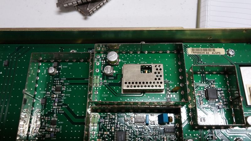
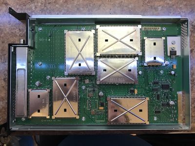
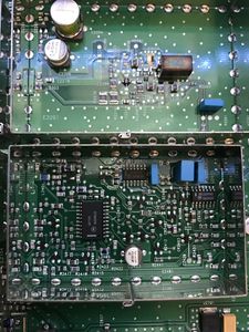
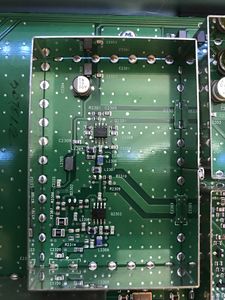
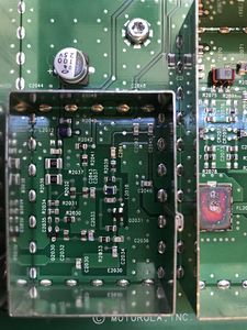
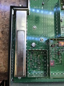
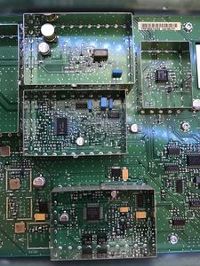
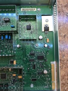
The receiver is pictured below. The 800/900 receiver differs from all others as it's half width and includes an internal preselector. The preselector is soldered on to the board and not tune-able as in the VHF/UHF modules.
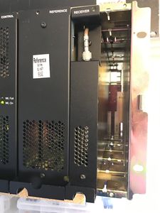
800 MHz Receiver - 0241
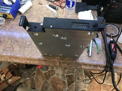
800 MHz Receiver - 0242


The receiver is a low side injection with the 1st Lo operating +73.35 MHz lower than the receiver frequency. There is no CPU on board like there is in the exciter as the SCM talks to the PLL chip (U2401) directly.
There is a 7 pole preselector in the front end prior to the first RF amplifier. This has about a 1.5 db insertion loss with a very good roll off. I'm actually surprised it's as good as it is, 1.5 dB is low for a ceramic filter.
Quantar 800 Mhz Preselector Narrow sweep
800 MHz Quantar Receiver Preselector Wide Sweep
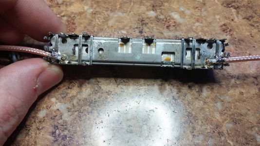
800 MHz Preselector 2
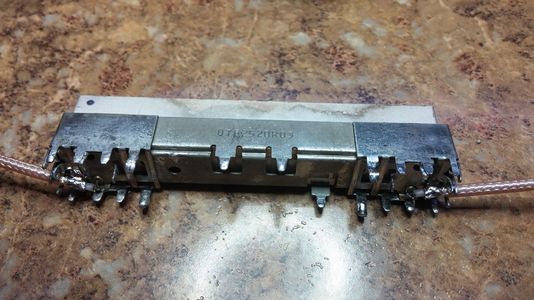
800 MHz Preselector 1


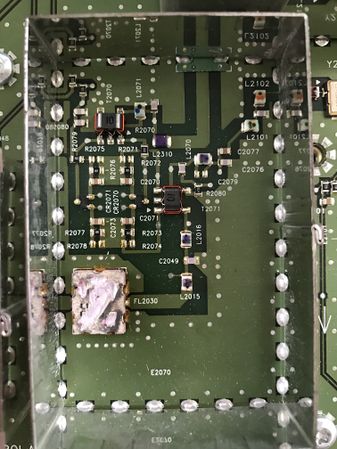
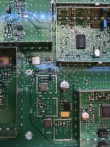
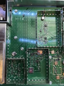
There is a image filter (FL2030) which filters the input to the double balanced mixer to prevent the RF radiating out the antenna port.
800MHz Receiver Image Filters
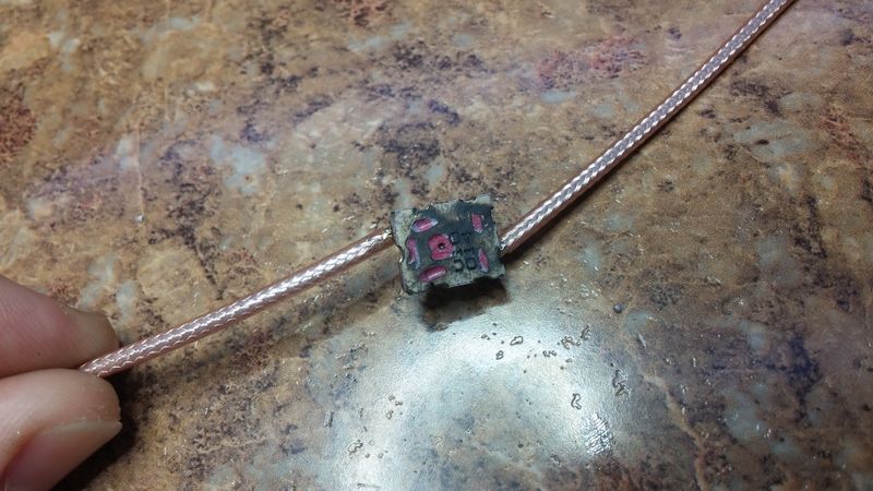
800 MHz RX Image Filter
800 MHz RX Image Filter
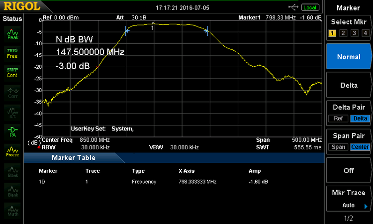
FL2030 response


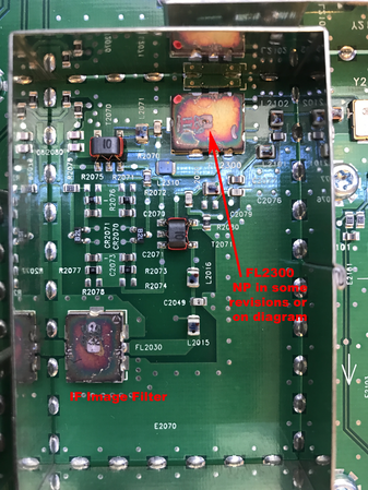
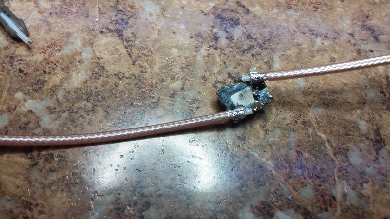
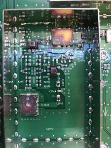
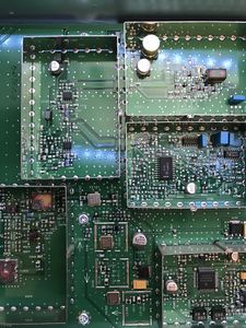
In the second 800 MHz board I looked at, (TRF6551G39) there is another filter (FL2300) which is on the input to the mixer from the Local Oscillator output. This is not present in the first board I converted (TRF6551J), and just has a 50 ohm line in place of it. It remains to be seen what this filter does. It needs to be removed and swept for response.
800 MHz Receiver TRF6551G39 - Image Filter
800 MHz Receiver TRF6551J - Image Filter
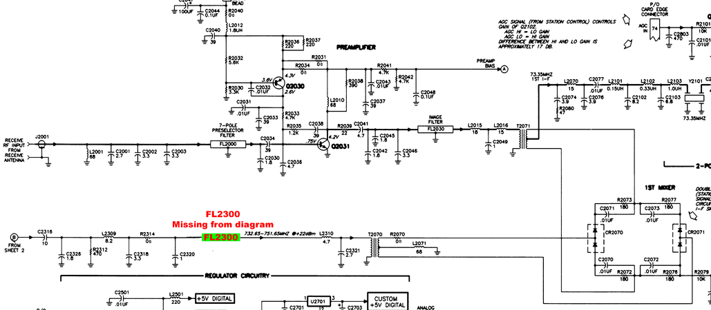
800 MHz Receiver TRF6551H diagram FL2300


Programing ROM
The SCM knows what type of module is inserted by reading voltage divider resistors on the u2600 A/D Converter. Some of these are on ports used for other things, Change Frequency and Lock and then A8 input is used for ID. The R2816 and R2815 form a voltage divider feeding the A8 input with the computed voltage in volts.
| Range | R2422 Chg Freq | R2414 Lock | SPACE | R2816 | R2815 | A8 Volts |
|---|---|---|---|---|---|---|
| 900 | 0 | 0 | 1200 | 4700 | 4.0 | |
| 800 | 0 | 0 | 1200 | 2700 | 3.5 |
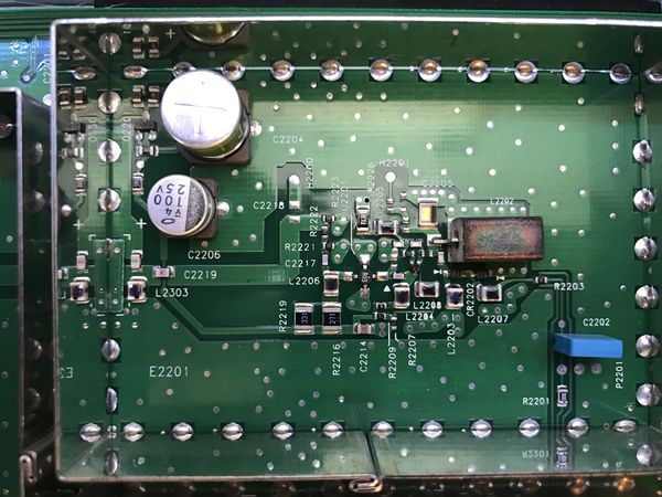
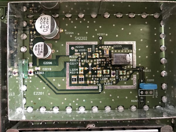
VCO
The VCO in the 800 differs from the 900 unit in that the 800 VCO does not have a soldered on shield over it. I'm not sure what difference this makes in practical use. Note on the TRF6551J unit there is a solder mask which would fit a shield.
900 MHz RX VCO shield
800 MHz VCO no shield
800 MHz Receiver TRF6551J - VCO showing shield mask]]


As the VCO runs at 73.35 MHz lower than the intended receive frequency the VCO will expect to lock over 726.65-752.65. Typically this will have extra range at either side of the VCO. C2205 is a laser cut tuning cap which is tuned at the factory to bring the unit up to a proper resonate frequency. Removing material (removing capacitance) raises the frequency of the VCO.
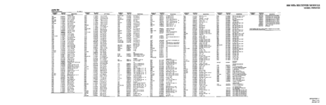
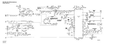
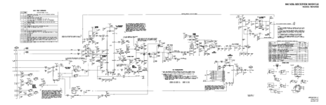
Service Manual
The service manual excerpt is in PDF and below.
800 MHz Receiver Model TRF6551 Service Manual Excerpt
In PNG format.
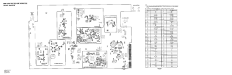
800 MHz Receiver Diagram 1
800 MHz Receiver Diagram 2
800 MHz Receiver Diagram 3
800 MHz Receiver Diagram 4


Pictures
800 MHz Receiver 1
800 MHz Receiver 2
800 MHz Receiver 3

800 MHz Receiver 4
800 MHz Receiver 5
800 MHz Receiver 6
800 MHz Receiver 7
800 MHz Receiver 8
800 MHz Receiver 9
800 MHz Receiver 10
800 MHz Receiver 11
800 MHz Receiver 12
800 MHz Receiver 13
800 MHz Receiver 14
800 MHz Receiver 15
800 MHz Receiver 16
800 MHz Receiver 17
800 MHz Receiver 18


Conversions
Converting to the 800 MHz to 900 MHz receiver works best if you plan to use an external preselector/pre-amp as the losses on 900 MHz are high. 100' of 7/8" heliax has just under 1.2 dB of loss, and 6' of RG-400 is 1 dB. It's completely possible to have 6' of interconnect cable between the duplexers and filters, and installing a pre-amp as close to the preselctor as possible will negate most of this loss.
800 to 900 MHz
The basic premise of converting the 800 to a 900 is four major parts:
- Convert the VCO for the proper frequency coverage
- Remove/Modify the ceramic preselector
- Change the module ID
- Test the unit.
It's important to have a known good working unit on 800 before starting work. If it is not working at it's intended frequency, fix it first.
It would be good to become very familiar with the schematic and service manual before attempting this.
Tools and test equipment you should have (not an exhaustive list)
- Hot air station
- Under board pre-heater
- 1000W heat gun and tips (for preselector removal)
- High quality soldering iron (metcal)
- Dual voltage variable DC supply
- Spectrum analyzer and probes
- Service monitor
- Experience working with SMD and reflow techniques
Converting VCO
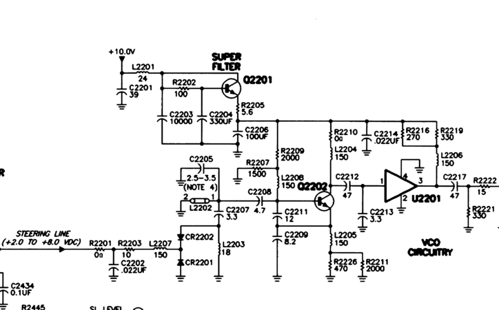
There is a single VCO for both the 800 and 900 bands. This is in contrast to the UHF and VHF modules which use two VCO to cover the entire band. The VCO (Q2202) consists of a tuned coax resonator shorted on one end (L2202) in resonance with parallel capacitors (C2211 & C2209) and laser cut tuning capacitor (C2205).
As this is a low side injection receiver the VCO runs 73.35 MHz below the intended signal. This is different from the high side injection systems used on VHF and UHF. Low side injection is less of an issue on 800/900 as traditionally there are no users on the image frequencies (+73 MHz) of any real ERP to cause interference.
- Mask off the VCO using Krapton tape and/or aluminum foil. The electrolytic caps don't do well with excess heat, especially as most are 10-15 years old at this point.
800 MHz Receiver vco diagram
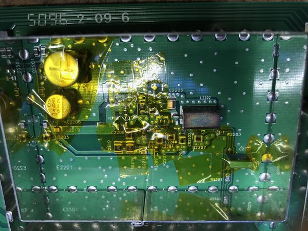
800 MHz Receiver VCO taped off for desoldering


- Setup the board with an under board pre-heater set to 460f. This is important as you want the board to warm up to close to the melting point of solder. Then the hot air wand will heat it the rest of the way.

Underboard pre-heater

- Once you have this preheated for a few minutes, use the hot air wand with no tip at 15 L/m and 650f on the coax resonator (L2202). Move it in a circular pattern while waiting on it to reflow. Once it's flowed, pull the resonator up and allow it to cool on an insulated pad. You don't want to thermal shock it, as it will crack being it's ceramic.
Careful you don't disturb any of the VCO parts, as they will most likely be reflowed. If you do, don't panic, just look at the before picture and put everything back to how it was on the VCO. It's a pretty easy circuit to figure out.
- While the VCO is still Warm, remove L2201 and set asside. This will allow us to power the VCO with out powering the rest of the receiver.
- Change the following parts in the VCO area.
| Part number | 800 | 900 | Notes |
|---|---|---|---|
| C2207 | 3.3 pF | 2.5 pF | INFO ONLY don't change, steering range |
| C2211 | 12 pF | 6.8 pF | Tank |
| C2209 | 8.2 pF | 5.6 pF | Tank |
| L2202 | 430 mils | 350 mils | Resonator |
| R2815 | 2100 | 4700 | ID resistor |
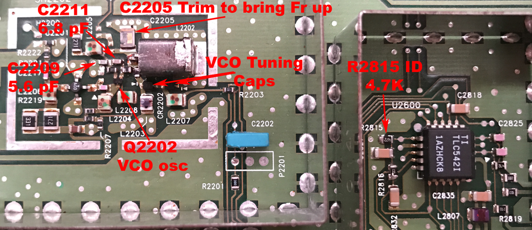
800 MHz Receiver VCO layout

- Now the VCO should be exposed and you can tack on some test wires to it while it cools down.
- Hook up to the VCO as shown.
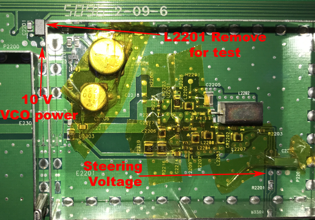
800 MHz Receiver VCO test points

- 10.0 V power to VCO on P2200 Pin #3
- 0-12 V on the steering line, P2201 #1
- output probe near the C2219 VCO output stripline. This doesn't need to be tacked on, just a probe near it so you can pickup the output on the spectrum analyzer.
Cutting down the Coaxial resonator
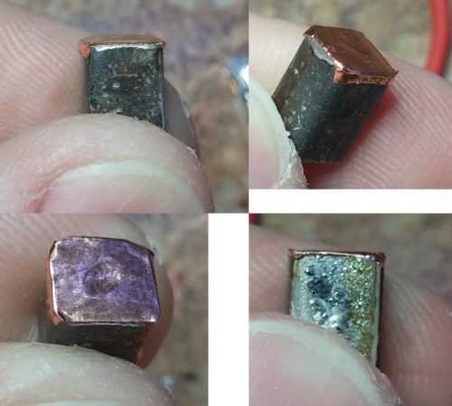
- The next step is to cut the coaxial resonator (L2202) down from the back side (the shorted, non leaded side) till it's 0.350" long.
You will need a diamond grinder to do this.
Once it's 350 mils long (5 mils longer is ok, shorter will require more trimming of C2205), fashion a copper tape strip and apply over the end of the resonator. This will need to be soldered in place around the edge and then soldered to the inside center conductor. This replaces the shorted out end which was ground off.
Resonator trimmed and shorted

- Reinstall the coaxial resonator
800 MHz Receiver VCO resonator installed

To arrive at the correct lengths the following measurements and parts changes were tried.
| !Parts changed | Resonator length (mils) | 0.5V | 5V | 9V | Delta |
|---|---|---|---|---|---|
| Resonator only | 390 | 739 | 766 | 785 | 46 |
| C2211 & C2209 | 390 | 755 | 786 | 807 | 52 |
| C2211 & C2209 | 350 | 785 | 820 | 841 | 56 |
| C2211/C2209 & trim C2205 | 350 | 809 | 849 | 874 | 65 |
It was found a combination of changing C2211, 2209 and grinding the resonator to 0.350" got the VCO to within 10 MHz of where it needed to be to cover the entire ham band and the commercial band just below it. This does make the coverage of the receiver larger than before, which is aventagious for amateur use, as it now covers the entire ham band. Sensitivity was found to drop off above 925 MHz however.
Tuning VCO
Tuning is needed to ensure we cover the proper range with the VCO. If we can't align the station due to the VCO not being locked in the commercial band, being locked in the ham band does not count.
A few points about VCO tuning:
- The VCO will be 73.35 MHz lower than the intended receiver frequency
- the sweet spot for the VCO steering voltage is 2.5-7.5 v
- each VCO is designed to cover half the range of the quantar.
- with the shield on they move up about 1.5 MHz
- from hot to cold Fr changes about 1 to 2 MHz. Hotter makes Fr go down, cool makes it go up.
- removing capacitance makes Fr go up.
- removing inductance makes Fr go up.
- tune a bit below the frequency (5-10 MHz) and adjust the tuning cap and a grinder tool (C2205)
- Get it close, I'm a perfectionist, but really 1-2 MHz from idea will not matter.
- at higher steering voltages (>9v) the VCO may get dirty. This is normal.
Put 5.0v on the steering line and note the frequency on the spectrum analyzer. You can sweep it from low to high and check the coverage is correct per the table above (it will be about 2MHz higher with the case off).
We're going to align it for a center frequency of 835 MHz. The reason for this is the VCO needs to cover 815-860 (888-933 MHz receiver freq), making the center 838, but with the shield off the resonate frequency lower by ~2 MHz, and we want to be able to tune this out. The shield adds capacitance to the circuit and this ups the resonate frequency.
While monitoring the VCO output on the spectrum analyzer, use a diamond tip Dremmel grinder and remove some of the high impedance end tuning cap on the VCO. Go a very little at a time, it makes a big difference. Use this to bring the VCO frequency up to 835 on the dot. It's normal for the VCO to jump a couple hundred KHZ or so depending on the stability of your power supply. There is no PLL running to lock it.
Do a sweep according and ensure it covers the intended range, 815-860 MHz. You want the coverage to be in the sweet spot of 2.5v to 7.5v, if it's not re-adjust it, but keep in mind it's easier to bring the resonate frequency up by removing material than make it go lower by adding material.
Clean it with some solvent and let it dry.
Removing the Preselector
The preselector is a large heat sink on the board, and will require advanced SMD experience to remove. Once it's removed it will be jumped out using a section of miniature coax (RG-393).
- The first step is to mask off the rest of the board to prevent damage due to the heat required to reflow the shield and preselector
- re-install the shields on the cases near the preselector assembly and tape the few exposed compounits
800 MHz Receiver Preselector Removal

- tape aluminum foil heat shield over the exposed board
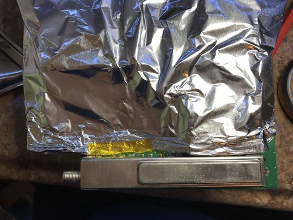
800 MHz Receiver Preselector Removal - 0270
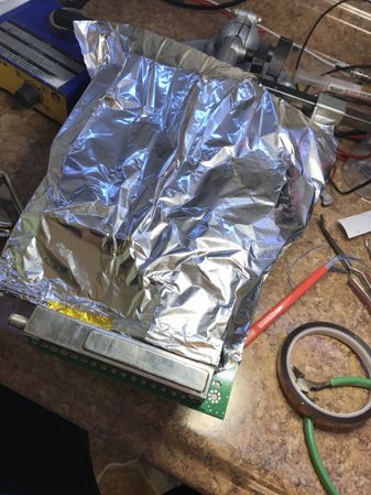
800 MHz Receiver Preselector Removal - 0272


- turn on your pre-heater under the board and let it warm up for 5-10 minutes, as you don't want to thermal shock the preselector
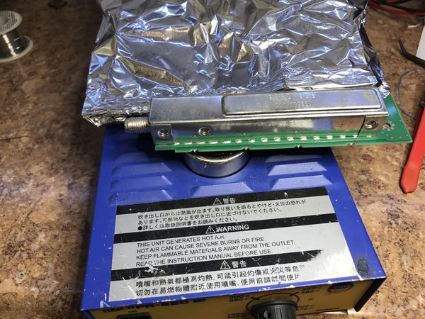
800 MHz Receiver Preselector Removal - 0274

- using the 1000W heat gun and tip, reflow the shield. keep the heat gun moving, this can DESTROY the board if done improperly. Once it's reflowed, remove the shield and set it asside.
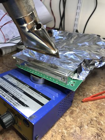
800 MHz Receiver Preselector Removal - 0277

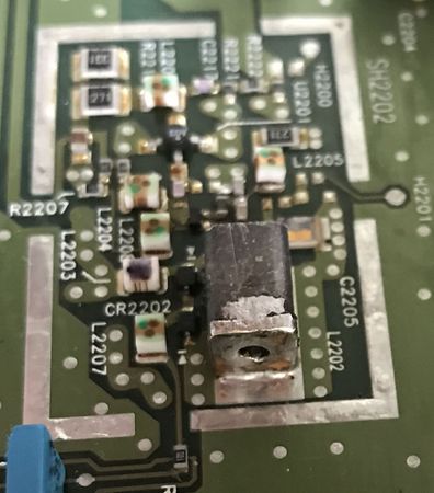
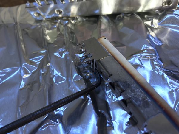
- Now while keeping heat on the preselector evenly pull it up buy using a pick or tongs. DO NOT grip it by the exposed ceramic material or cause undo pressure to be applied to it, or it may crack.
800 MHz Receiver Preselector Removal - 0281

- Set the Preselector aside an allow it to cool naturally, as it may crack if thermal shocked.
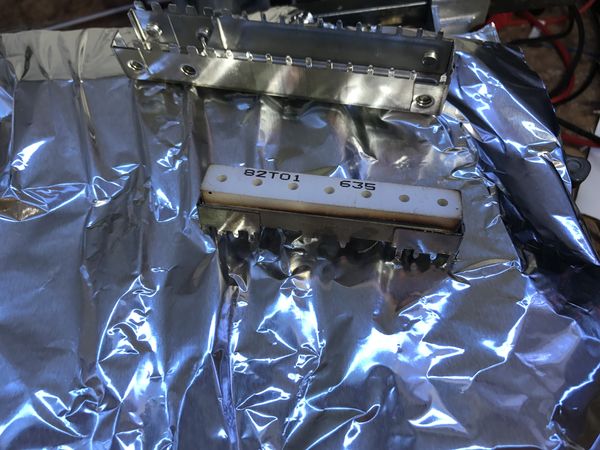
800 MHz Receiver Preselector Removal - 0290

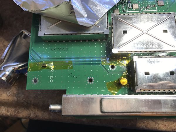
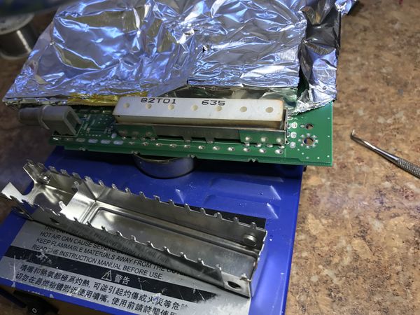
- note some the preselector "carrier" parts may have reflowed and moved. This is only a concern if you want to re-install it at further date.
800 MHz Receiver Preselector Removal - 0299
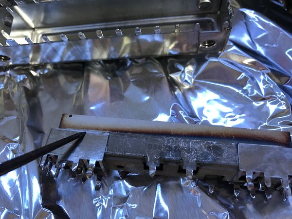
800 MHz Receiver Preselector Removal - 0297


- Allow the board to cool. It's optional if you want to clean up the solder on the underside of the board, I normally leave it.
- once cooled, install a coax jumper across the pads of the preselector
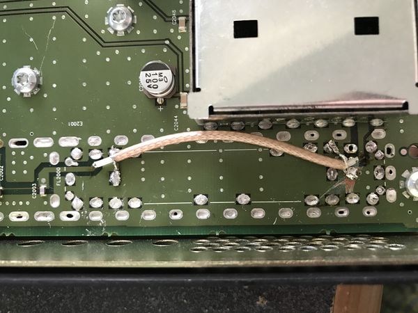
800 MHz Receiver preselector jumper TRF6551J - 0306

Preselector modification
There have been a couple attempts at modifying the preselector by the same method used on the VCO resonator. A couple have been broken due to the thermal shock.
the 800 MHz preselector is 36 MHz wide centered on 814.5 MHz.
The height including the "chassis" is 0.585"
removing .050" making it .535" total, moved the CF to 890 MHz which might have worked. More research needs to be done.
Results
The following results were obtained from a unit converted which did not have the extra filter between the VCO amp and the Mixer. A conversion of one of these extra FL3200 units has not been attempted at this point.
This was using a 12dB SINAD for NBFM 1.5 KHz 1kc tone deviation. The voltages were measured from the test screen in the quantar software. I've noted this as the quantar reads it's steering voltage about 0.5v low.
There is a pronounced roll-off above 915 MHz, which may be due to the image filter (FL2030). As this covers both 25 and 12 MHz split repeaters in the ham band, further experimentation was not attempted. If you find out what is limiting this and how to overcome it for full ham band performance please update this wiki.
| Frequency | VCO voltage | After Mod |
|---|---|---|
| 885 | Unlock | NA |
| 890 | 1.06v | -121.0 dBm |
| 895 | 1.57v | -121.0 dBm |
| 900 | 2.04v | -121.0 dBm |
| 902 | 2.27v | -121.2 dBm |
| 905 | 2.63v | -121.5 dBm |
| 910 | 3.18v | -121.5 dBm |
| 915 | 3.84v | -121.5 dBm |
| 925 | 5.26v | -119.7 dBm |
| 927 | 5.53v | -119.2 dBm |
| 930 | 6.00v | -117.7 dBm |
| 935 | 6.79v | -116.2 dBm |
| 940 | 7.57v | -114.7 dBm |
| 948 | 8.55v | -112.6 dBm |
| 950 | Unlock | NA |
Final testing
Once the preceding modifications have been done it's time to test the receiver module.
With the power off install the RX board back in the metal case and slot it into the Quantar chassis.
Power the station on and program a test code plug.
Use the control and metering screen to check the oscillator voltage at each frequency. Ideally you should be between 2 and 7.5 volts for 896.00-940.00. If your minimum lock voltage is under 1.5v you may want to re-adjust the VCO in question. If the high frequency is above 8v you may wish to adjust as well.
Check the sensitivity of the receiver at all locked frequencies. The sensitivity should be better than -120.5 dBm or .225μV for 12dB SINAD in NBFM. Motorola quotes the WBFM sensitivity for 900 MHz as .35μV which is -116 dBm or better, but this includes the preselector (1.5 dB loss).
Once this is verified, button it up, install the modified preselector and mark the unit as a 800 modified to 900.
Congratulations and please report back with your findings!