Difference between revisions of "XTL Radio"
Jump to navigation
Jump to search
| Line 8: | Line 8: | ||
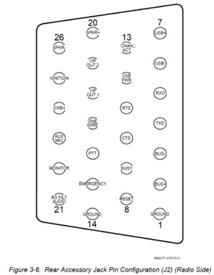
Here's a picture of it from the radio side | Here's a picture of it from the radio side | ||
| + | [[File:XTL Accessory Jack Picture from Install Guide.png|300px|frameless|center|XTL Accessory Jack Picture Radio Side, aka J2]] | ||
== Table of Pins == | == Table of Pins == | ||
| Line 54: | Line 55: | ||
Pictures of the XTL Accessory Connector - 027.JPG | Pictures of the XTL Accessory Connector - 027.JPG | ||
</gallery> | </gallery> | ||
| + | |||
| + | = Manuals = | ||
| + | [[File:XTL1500 Install Manual.pdf|thumb|Xtl-1500-install-manual-6815851h01-o]] | ||
| + | [[File:XTL2500 Detailed Service Manual.pdf|thumb|XTL2500 Detailed Service Manual]] | ||
| + | [[File:XTL5000 Basic Service Manual.pdf|thumb|XTL5000 Basic Service Manual]] | ||
Revision as of 00:56, 12 May 2020
Page covering the XTL 1500/2500/5000 Radios
These are P25 trunking radios which are mono-band.
Contents
Accessory Connector
J2 is the accessory connector
Here's a picture of it from the radio side

Table of Pins
Sourcing of connector
As of now, there is no other source for the connector than Motorola.
The body looks like 2 D-Sub connectors stacked with standard pitch spacing on the pins.
Aftermarket Pins will not work due to the low profile retaining ring. This thread on the Batlabs Batboard has some more info and this picture showing the differences below:

Photos of connector
I disassembled and took some close up pictures with my scope. The connector looks a bit similar to most D-SUB connectors.