UHF Receiver
This page covers the Range 1 to Range 4 receivers. The Range 0 is a newer (and easier to modify) design.
Basics
The basic receiver is pictured below. Note the UHF R1-R4 receivers have a preselector that's flush with the front panel and only 3 adjustment. This is a dead give away that you have a UHF R1-R4 from the front. Unfortunately there is not an easy way to identify it further than by part number.
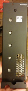
UHF RX Front
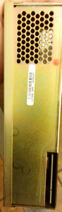
UHF RX Back
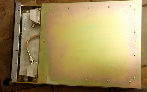
UHF RX Case
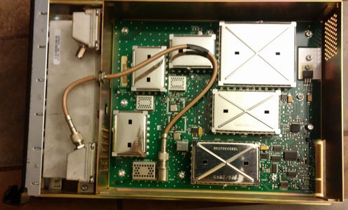
UHF RX Internal


The receiver is a high side injection with the 1st Lo operating +73.35 MHz higher than the receiver frequency.
The SCM knows what type of module is inserted by reading voltage divider resistors on the u2600 A/D Converter. Some of these are on ports used for other things, Change Frequency and Lock and then A8 input is used for ID. Note the resistors have the same labels on the UHF boards but on other bands the same parts have different labels. The R2606 and R2607 form a voltage divider feeding the A8 input with the computed voltage in volts.
| Range | R2449 Chg Freq | R2450 Lock | SPACE | R2606 | R2607 | A8 Volts |
|---|---|---|---|---|---|---|
| UHF R0 | 0 | 3300 | 5600 | 3300 | 1.9 | |
| UHF R1 | 0 | 0 | 1200 | 1200 | 2.5 | |
| UHF R2 | 0 | 3300 | 1200 | 1200 | 2.5 | |
| UHF R3 | 3300 | 0 | 1200 | 1200 | 2.5 | |
| UHF R4 | 3300 | 3300 | 1200 | 1200 | 2.5 | |
| VHF | R2413 | R2415 | R2812 | R2814 | ||
| VHF R1 | 0 | 0 | 2700 | 1200 | 1.5 | |
| VHF R2 | 0 | 3300 | 2700 | 1200 | 1.5 | |
| 800/900 | R2422 | R2414 | R2816 | R2815 | ||
| 900 | 0 | 0 | 1200 | 4700 | 4.0 | |
| 800 | 0 | 0 | 1200 | 2700 | 3.5 |
The service manual excerpt is in PDF and below.
UHF Receiver Models TRE6281-TRE6282-TRE6283-TRE6284 Service Manual Excerpt
In PNG format.
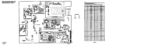
Schematic Sheet 1 of 4
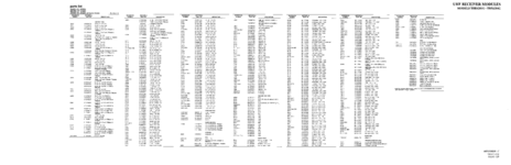
Schematic Sheet 2 of 4
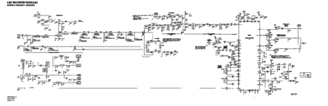
Schematic Sheet 3 of 4
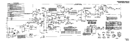
Schematic Sheet 4 of 4


Note on the schematic the VCO high and Low are reversed. This seems to be a recurring theme in the Quantar manuals.

As the VCO runs at 73.35 MHz higher than the intended receive frequency the VCO will expect to lock over the following ranges. The ideal spot for the VCO to opperate is between 2.5 and 7.5 Volts highlighted in pink below.
| Range | Lower VCO | Upper VCO | ||||||||
|---|---|---|---|---|---|---|---|---|---|---|
| Volts | 0.8 | 2.5 | 5.0 | 7.5 | 9.2 | 0.8 | 2.5 | 5.0 | 7.5 | 9.2 |
| UHF R1 | 462 | 467 | 479 | 491 | 499 | 478 | 491 | 499 | 506 | 514 |
| UHF R2 | 498 | 511 | 519 | 527 | 536 | 514 | 527 | 535 | 543 | 552 |
| UHF R3 | 528 | 543 | 549 | 555 | 564 | 541 | 555 | 561 | 567 | 575 |
| UHF R4 | 553 | 567 | 574 | 580 | 589 | 568 | 580 | 587 | 593 | 601 |
The VCO is much like the VCO in the exciter, a sealed unit with no further diagram available from the factory.